Dewalt DC825B Instruction Manual - Page 2
Save These Instructions For Future Use - battery
 |
View all Dewalt DC825B manuals
Add to My Manuals
Save this manual to your list of manuals |
Page 2 highlights
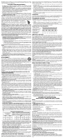
• Do not use an extension cord unless it is absolutely necessary. Use of improper extension cord could result in risk of fire, electric shock, or electrocution. • When operating a power tool outdoors, use an extension cord suitable for outdoor use. Use of a cord suitable for outdoor use reduces the risk of electric shock. • An extension cord must have adequate wire size (AWG or American Wire Gauge) for safety. The smaller the gauge number of the wire, the greater the capacity of the cable, that is 16 gauge has more capacity than 18 gauge. An undersized cord will cause a drop in line voltage resulting in loss of power and overheating. When using more than one extension to make up the total length, be sure each individual extension contains at least the minimum wire size. The following table shows the correct size to use depending on cord length and nameplate ampere rating. If in doubt, use the next heavier gauge. The smaller the gauge number, the heavier the cord. Ampere Rating More Than 0 6 10 12 Not More Than 6 10 12 16 Minimum Gauge for Cord Sets Volts Total Length of Cord in Feet (meters) 120V 25 (7.6) 50 (15.2) 100 (30.5) 150 (45.7) 240V 50 (15.2) 100 (30.5) 200 (61.0) 300 (91.4) AWG 18 16 16 14 18 16 14 12 16 16 14 12 14 12 Not Recommended • Do not place any object on top of charger or place the charger on a soft surface that might block the ventilation slots and result in excessive internal heat. Place the charger in a position away from any heat source. The charger is ventilated through slots in the top and the bottom of the housing. • Do not operate charger with damaged cord or plug. • Do not operate charger if it has received a sharp blow, been dropped, or otherwise damaged in any way. Take it to an authorized service center. • Do not disassemble charger; take it to an authorized service center when service or repair is required. Incorrect reassembly may result in a risk of electric shock, electrocution or fire. • Disconnect the charger from the outlet before attempting any cleaning. This will reduce the risk of electric shock. Removing the battery pack will not reduce this risk. • NEVER attempt to connect 2 chargers together. • The charger is designed to operate on standard 120V household electrical power. Do not attempt to use it on any other voltage. This does not apply to the vehicular charger. Using Automatic Tune-Up™ Mode The automatic Tune-Up™ Mode equalizes or balances the individual cells in the battery pack allowing it to function at peak capacity. Battery packs should be tuned up weekly or after 10 charge/discharge cycles or whenever the pack no longer delivers the same amount of work. To use the automatic Tune-Up™, place the battery pack in the charger and leave it for at least 8 hours. The charger will cycle through the following modes. 1. The red light will blink continuously indicating that the 1-hour charge cycle has started. 2. When the 1-hour charge cycle is complete, the light will stay on continuously and will no longer blink. This indicates that the pack is fully charged and can be used at this time. 3. If the pack is left in the charger after the initial 1-hour charge, the charger will begin the Automatic Tune-Up™ mode. This mode continues up to 8 hours or until the individual cells in the battery pack are equalized. The battery pack is ready for use and can be removed at any time during the Automatic Tune-Up™ mode. 4. Once the Automatic Tune-Up™ mode is complete, the charger will begin a maintenance charge; the red indicator will remain lit. Chargers Your tool uses a DEWALT 7.2, 9.6, 12, 14,4 or 18 volt charger. Be sure to read all safety instructions before using your charger. Consult the chart at the end of this manual for compatibility of chargers and battery packs. Charging Procedure DANGER: Electrocution hazard. 120 volts present at charging terminals. Do not probe with conductive objects. Danger of electric shock or electrocution. 1. Plug the charger into an appropriate outlet before inserting battery pack. 2. Insert the battery pack into the charger. The red (charging) light will blink continuously indicating that the charging process has started. 3. The completion of charge will be indicated by the red light remaining ON continuously. The pack is fully charged and may be used at this time or left in the charger. Indicator Light Operation Charge Indicators Some chargers are designed to detect certain problems that can arise with battery packs. Problems are indicated by the red light flashing at a fast rate. If this occurs, re-insert battery pack into the charger. If the problem persists, try a different battery pack to determine if the charger is OK. If the new pack charges correctly, then the original pack is defective and should be returned to a service center or other collection site for recycling. If the new battery pack elicits the same trouble indication as the original, have the charger tested at an authorized service center. HOT/COLD PACK DELAY Some chargers have a Hot/Cold Pack Delay feature: when the charger detects a battery that is hot, it automatically starts a Hot Pack Delay, suspending charging until the battery has cooled. After the battery has cooled, the charger automatically switches to the Pack Charging mode. This feature ensures maximum battery life. The red light flashes long, then short while in the Hot Pack Delay mode. PROBLEM POWER LINE Some chargers have a Problem Power Line indicator. When the charger is used with some portable power sources such as generators or sources that convert DC to AC, the charger may temporarily suspend operation, flashing the red light with two fast blinks followed by a pause. This indicates the power source is out of limits. LEAVING THE BATTERY PACK IN THE CHARGER The charger and battery pack can be left connected with the red light glowing indefinitely. The charger will keep the battery pack fresh and fully charged. NOTE: A battery pack will slowly lose its charge when kept out of the charger. If the battery pack has not been kept on maintenance charge, it may need to be recharged before use. A battery pack may also slowly lose its charge if left in a charger that is not plugged into an appropriate AC source. WEAK BATTERY PACKS: Chargers can also detect a weak battery pack. Such batteries are still usable but should not be expected to perform as much work. The charger will indicate to replace battery pack. Important Charging Notes 1. Longest life and best performance can be obtained if the battery pack is charged when the air temperature is between 65°F and 75°F (18°- 24°C). DO NOT charge the battery pack in an air temperature below +40°F (+4.5°C), or above +105°F (+40.5°C). This is important and will prevent serious damage to the battery pack. 2. The charger and battery pack may become warm to touch while charging. This is a normal condition, and does not indicate a problem. To facilitate the cooling of the battery pack after use, avoid placing the charger or battery pack in a warm environment such as in a metal shed, or an uninsulated trailer. 3. If the battery pack does not charge properly: a. Check current at receptacle by plugging in a lamp or other appliance; b. Check to see if receptacle is connected to a light switch which turns power off when you turn out the lights; c. Move charger and battery pack to a location where the surrounding air temperature is approximately 65°F - 75°F (18°- 24°C); d. If charging problems persist, take the tool, battery pack and charger to your local service center. 4. The battery pack should be recharged when it fails to produce sufficient power on jobs which were easily done previously. DO NOT CONTINUE to use under these conditions. Follow the charging procedure. You may also charge a partially used pack whenever you desire with no adverse affect on the battery pack. 5. Under certain conditions, with the charger plugged into the power supply, the exposed charging contacts inside the charger can be shorted by foreign material. Foreign materials of a conductive nature such as, but not limited to, grinding dust, metal chips, steel wool, aluminum foil, or any buildup of metallic particles should be kept away from charger cavities. Always unplug the charger from the power supply when there is no battery pack in the cavity. Unplug charger before attempting to clean. 6. Do not freeze or immerse charger in water or any other liquid. WARNING: Shock hazard. Don't allow any liquid to get inside charger. Electric shock may result. CAUTION: Never attempt to open the battery pack for any reason. If the plastic housing of the battery pack breaks or cracks, return to a service center for recycling. Storage Recommendations 1. The best storage place is one that is cool and dry away from direct sunlight and excess heat or cold. 2. Long storage will not harm the battery pack or charger. Under proper conditions, they can be stored for 5 years or more. SAVE THESE INSTRUCTIONS FOR FUTURE USE Motor Voltage decrease of more than 10% will cause loss of power and overheating. All DEWALT tools are factory tested; if this tool does not operate, check your battery pack. COMPONENTS (Fig. 3) WARNING: Never modify the power tool or any part of it. Damage or personal injury could result. A. Trigger switch G. Anvil B. Rocker switch (DW059) H. Hog ring C. Forward/reverse button I. Battery release buttons D. Chuck collar J. Worklight E. 1/4" hex quick-release chuck K. Belt hook (optional accessory) F. Detent pin INTENDED USE These heavy-duty impact wrench/drivers are designed for professional impact screwdriving applications. The impact function makes this tool particularly useful for driving fasteners in wood, metal and concrete. DO NOT use under wet conditions or in presence of flammable liquids or gases. FIG. 1 FIG. 2 FIG. 3 D E J A I G C B K L DW059 I FIG. 4 D E FIG. 5 G FIG. 6 G F DC820, DC822, DC830, DC840 H DC823, DC833, DC841 These heavy-duty impact wrench/drivers are professional power tools. DO NOT let children come into contact with the tool. Supervision is required when inexperienced operators use this tool. Belt Hook (Optional Accessory) WARNING: To reduce the risk of serious personal injury, DO NOT suspend tool overhead or suspend objects from the belt hook. ONLY hang tool's belt hook from a work belt. WARNING: To reduce the risk of serious personal injury, ensure the screw (L) holding the belt hook is secure. The belt hook (K) can be be attached to either side of the tool to accommodate left- or righthanded users. If the hook is not desired at all, it can be removed from the tool. To move belt hook, remove the screw (L) that holds the belt hook in place then reassemble on the opposite side. OPERATION WARNING: To reduce the risk of serious personal injury, turn tool off and disconnect battery pack before making any adjustments or removing/installing attachments or accessories. Installing and Removing the Battery Pack NOTE: Make sure your battery pack is fully charged. To install the battery pack into the tool handle, align the base of the tool with the notch inside the tool's handle (Fig. 2) and slide the battery pack firmly into the handle until you hear the lock snap into place. To remove the battery pack from the tool, press the release buttons (I) and firmly pull the battery pack out of the tool handle. Insert it into the charger as described in the charger section of this manual. Switch - DW059 (Fig. 3) Pressing the BOTTOM part of the rocker switch (B) runs the tool in forward (right hand thread) direction. Pressing the TOP of the switch reverses motor direction. This allows "rocking" fasteners to break them loose. Variable Speed Trigger Switch (Fig. 3) To turn the tool on, squeeze the trigger switch (A). To turn the tool off, release the trigger switch. Your tool is equipped with a brake. The chuck will stop as soon as the trigger switch is fully released. The variable speed switch enables you to select the best speed for a particular application. The more you squeeze the trigger, the faster the tool will operate. Use lower speeds for starting holes without a center punch, drilling in metals or plastics, or driving screws. For maximum tool life, use variable speed only for starting holes or fasteners. NOTE: Continuous use in variable speed range is not recommended. It may damage the switch and should be avoided. Forward/Reverse Control Button (Fig. 3) A forward/reverse control button (C) determines the direction of the tool and also serves as a lock off button. To select forward rotation, release the trigger switch and depress the forward/reverse control button on the right side of the tool. To select reverse, depress the forward/reverse control button on the left side of the tool. The center position of the control button locks the tool in the OFF position. When changing the position of the control button, be sure the trigger is released. NOTE: The first time the tool is run after changing the direction of rotation, you may hear a click on start up. This is normal and does not indicate a problem. Worklight (Fig. 3) There is a worklight (J) located just above the trigger switch (A). The worklight will be activated when the trigger switch is squeezed. NOTE: The worklight is for lighting the immediate work surface and is not intended to be used as a flashlight. Quick-Release Chuck (Fig. 4) DC825, DC827, DC835, DC845, DC855, DCF826 NOTE: The chuck accepts 1/4" (6.35 mm) hex accessories only. Place the switch in the locked off (center) position or remove battery pack before changing accessories. To install an accessory, pull the chuck collar (D) away from the front of the tool, insert the accessory and release the collar. The accessory is locked in place. To remove an accessory, pull the chuck collar away from the front of the tool. Remove the accessory and release the collar. Anvils CAUTION: Use only impact sockets. Non-impact sockets may break and cause a hazardous condition. Inspect socket prior to use to ensure that it contains no cracks. Place the switch in the locked off (center) position or remove battery pack before changing accessories. ANVIL WITH DETENT PIN (FIG. 5) DC820, DC821, DC822, DC830, DC840, DW059 To install a socket on the anvil, align the hole in the side of the socket with the detent pin (F) on the anvil (G). Press the socket on until the detent pin engages in the hole. Depression of detent pin may be necessary to aid installation of socket. To remove a socket, depress the detent pin through the hole and pull the socket off. ANVIL WITH HOG RING (FIG. 6) DC823, DC833, DC841 To install a socket on the hog ring anvil, firmly push socket onto the anvil (G). The hog ring (H) compresses to allow the socket to slide on. After the socket is installed, the hog ring applies pressure to help provide socket retention. To remove a socket, grasp the socket and firmly pull it off. Usage Your impact tool generates the following output torque: Cat # Ft.-Lbs. In.-Lbs. Nm Cat # Ft.-Lbs. In.-Lbs. Nm DC820 145 1740 195 DC833 111 1330 150 DC821 160 1920 215 DC835 103 1240 140 DC822 145 1740 195 DC840 120 1440 160 DC823 120 1440 160 DC841 105 1260 145 DC825 111 1330 150 DC845 96 1150 130 DC827 111 1330 150 DC855 80 960 110 DCF826 111 1330 150 DW059 300 3600 405 DC830 135 1620 180 CAUTION: Ensure fastener and/or system will withstand the level of torque generated by the tool. Excessive torque may cause breakage and possible personal injury. 1. Place the socket on the fastener head. Keep the tool pointed straight at the fastener. 2. Press switch to start operation. Always check torque with a torque wrench, as the fastening torque is affected by many factors including the following: • Voltage: Low voltage, due to a nearly discharged battery, will reduce fastening torque. • Socket size: Failure to use the correct socket size will cause a reduction in fastening torque. • Bolt Size: Larger bolt diameters generally require higher fastening torque. Fastening torque will also vary according to length, grade, and torque coefficient. • Bolt: Ensure that all threads are free of rust and other debris to allow proper fastening torque. • Material: The type of material and surface finish of the material will affect fastening torque. • Fastening Time: Longer fastening time results in increased fastening torque. Using a longer fastening time than recommended could cause the fasteners to be overstressed, stripped or damaged. MAINTENANCE WARNING: To reduce the risk of serious personal injury, turn tool off and disconnect battery pack before making any adjustments or removing/installing attachments or accessories.
-
 1
1 -
 2
2 -
 3
3 -
 4
4 -
 5
5 -
 6
6 -
 7
7
 |
 |
