Dewalt DCF620M2 Instruction Manual - Page 12
Variable Speed Switch Fig. 2, Forward/Reverse Control Lever Fig. 2, Worklight Fig. 2, Belt Hook Fig
 |
View all Dewalt DCF620M2 manuals
Add to My Manuals
Save this manual to your list of manuals |
Page 12 highlights
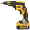
English INTENDED USE This screwdriver is designed for professional fastening applications. DO NOT use under wet conditions or in presence of flammable liquids or gases. This is a professional power tool. DO NOT let children come into contact with the tool. Supervision is required when inexperienced operators use this tool. DEAD SPINDLE ACTION All DEWALT drywall screwguns provide a dead spindle output to permit fasteners to be located easily on the driving accessory. Clutches are held apart by a light spring pressure permitting the driving clutch to rotate without turning the driven clutch and accessory. When sufficient forward pressure is applied to the unit, the clutches engage and rotate the spindle and accessories. A reversing switch makes it possible to drive or loosen either right or left hand fasteners. Variable Speed Switch (Fig. 2) To turn the tool "ON", squeeze the trigger switch (G). To turn the tool "OFF" release the trigger. Your tool is equipped with a variable speed switch which enables you to select the best speed for a particular application. The farther you squeeze the trigger, the faster the tool will operate. LOCK-ON BUTTON To lock the switch in the ON position for continuous operation, depress the trigger switch (G) and push up the lock-on button (I). The tool will continue to run. To turn the tool off, from a locked on condition, squeeze and release the trigger once. Before using the tool (each time), be sure that the locking button release mechanism is working freely. CAUTION: Be sure to release the locking mechanism before removing the battery from the tool. Failure to do so will cause the tool to start immediately the next time the battery is installed. Damage or injury could result. Forward/Reverse Control Lever (Fig. 2) A forward/reverse control lever (H) determines the direction of the tool and also serves as a lock-off. To select forward rotation, release the trigger switch and depress the forward/reverse control lever on the right side of the tool. To select reverse, release the trigger switch (G) and depress the forward/reverse control lever on the left side of the tool. The center position of the control lever locks the trigger switch (G) in the off position. When changing the position of the control button, be sure the trigger is released. NOTE: The first time the tool is run after changing the direction of rotation, you may hear a click on start up. This is normal and does not indicate a problem. Worklight (Fig. 2) There is a worklight (J) located on the foot of the tool. The worklight is activated when the trigger switch is depressed, and will automatically turn off 20 seconds after the trigger switch is released. If the trigger switch remains depressed, the worklight will remain on. NOTE: The worklight is for lighting the immediate work surface and is not intended to be used as a flashlight. Belt Hook (Fig. 2) WARNING: To reduce the risk of serious personal injury, DO NOT suspend tool overhead or suspend objects from the belt hook. ONLY hang tool's belt hook from a work belt. 10
-
 1
1 -
2
-
3
-
4
-
5
-
6
-
 7
7 -
 8
8 -
 9
9 -
 10
10 -
 11
11 -
 12
12 -
 13
13 -
 14
14 -
 15
15 -
 16
16 -
 17
17 -
18
-
19
-
20
-
21
-
22
-
23
-
24
-
25
-
26
-
27
-
28
-
29
-
30
-
31
-
32
-
33
-
34
-
35
-
36
-
37
-
38
-
39
-
40
-
41
-
42
-
43
-
44
-
45
-
46
-
47
-
48
-
49
-
50
-
51
-
52
 |
 |