Dewalt DCF880L2 Instruction Manual - Page 12
Variable Speed Trigger Switch Fig. 2, OPERATION, Installing and Removing the Battery Pack, Fig. 3
 |
View all Dewalt DCF880L2 manuals
Add to My Manuals
Save this manual to your list of manuals |
Page 12 highlights
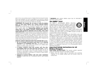
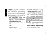
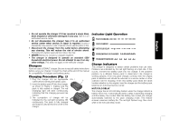
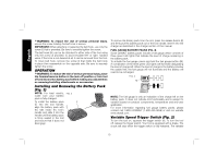
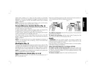
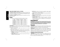
English WARNING: To reduce the risk of serious personal injury, ensure the screw holding the belt hook is secure. IMPORTANT: When attaching or replacing the belt hook, use only the screw (I) that is provided. Be sure to securely tighten the screw. The belt hook (H) can be be attached to either side of the tool using only the screw (I) provided, to accommodate left- or right- handed users. If the hook is not desired at all, it can be removed from the tool. To move belt hook, remove the screw (I) that holds the belt hook in place then reassemble on the opposite side. Be sure to securely tighten the screw. OPERATION WARNING: To reduce the risk of serious personal injury, place the forward/reverse button in the lock-off position or turn tool off and disconnect battery pack before making any adjustments or removing/installing attachments or accessories. Installing and Removing the Battery Pack (Fig. 3) NOTE: For best results, FIG. 3 make sure your battery pack is fully charged. To install the battery pack F (F) into the tool handle, align the battery pack with E the rails inside the tool's handle and slide it into the handle until the battery pack is firmly seated in the tool and ensure that it does not disengage. To remove the battery pack from the tool, press the release button (E) and firmly pull the battery pack out of the tool handle. Insert it into the charger as described in the charger section of this manual. FUEL GAUGE BATTERY PACKS (FIG. 4) Some DEWALT battery packs include a fuel gauge which consists of three green LED lights that indicate the level of charge remaining in the battery pack. To actuate the fuel gauge, press and hold the fuel gauge button (M). A combination of the three green LED lights will illuminate designating the level of charge left. When the level of charge in the battery is below the usable limit, the fuel gauge will not illuminate and the battery will need to be recharged. FIG. 4 M NOTE: The fuel gauge is only an indication of the charge left on the battery pack. It does not indicate tool functionality and is subject to variation based on product components, temperature and end-user application. For more information regarding fuel gauge battery packs, please contact call 1-800-4-DEWALT (1-800-433-9258) or visit our website www.dewalt.com. Variable Speed Trigger Switch (Fig. 2) To turn the tool on, squeeze the trigger switch (A). To turn the tool off, release the trigger switch. Your tool is equipped with a brake. The chuck will stop when the trigger switch is fully released. The variable 10
-
 1
1 -
2
-
3
-
4
-
5
-
6
-
 7
7 -
 8
8 -
 9
9 -
 10
10 -
 11
11 -
 12
12 -
 13
13 -
 14
14 -
 15
15 -
 16
16 -
 17
17 -
18
-
19
-
20
-
21
-
22
-
23
-
24
-
25
-
26
-
27
-
28
-
29
-
30
-
31
-
32
-
33
-
34
-
35
-
36
-
37
-
38
-
39
-
40
-
41
-
42
-
43
-
44
-
45
-
46
-
47
-
48
-
49
-
50
-
51
-
52
 |
 |