Dewalt DCR018 Instruction Manual - Page 10
COMPONENTS FIG. 2, OPERATION, Installing and Removing the Battery Pack, Fig. 3 - manual
 |
View all Dewalt DCR018 manuals
Add to My Manuals
Save this manual to your list of manuals |
Page 10 highlights
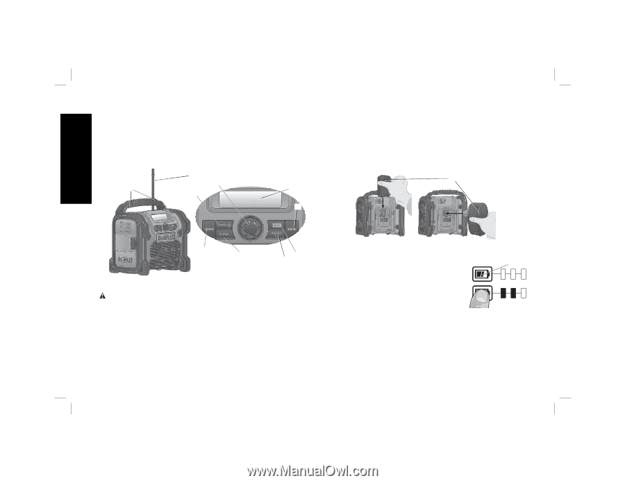
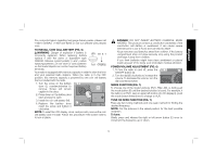
English COMPONENTS (FIG. 2) A. ON/OFF button F. Mode button B. Volume knob G. Clock button C. Antenna H. Preset button D. Hang holes I. LCD display E. Seek/tuner/arrow buttons FIG. 2 D C B A To install the battery pack (J), insert the slide pack or tower stem into battery receptical until the battery pack is firmly seated. For the stem pack, be sure that the battery latches are engaged. Refer to Figure 3. To remove battery pack from the radio, firmly pull up or out depending on the battery type. For the stem pack, press the battery release buttons before pulling firmly. Insert it into the charger as described in the charger section of this manual. FIG. 3 J I E E G F H OPERATION WARNING: To reduce the risk of injury, turn unit off and disconnect it from power source before installing and removing accessories, before adjusting or when making repairs. Installing and Removing the Battery Pack (Fig. 3) NOTE: For best results, make sure your battery pack is fully charged. FUEL GAUGE BATTERY PACKS (FIG. 4) Some DEWALT battery packs include a fuel FIG. 4 K gauge which consists of three green LED lights that indicate the level of charge remaining in the battery pack. To actuate the fuel gauge, press and hold the fuel gauge button (K). A combination of the three green LED lights will illuminate designating the level of charge left. When the level of charge in the battery is below the usable limit, the fuel gauge will not illuminate and the battery will need to be recharged. NOTE: The fuel gauge is only an indication of the charge left on the battery pack. It does not indicate unit functionality and is subject to variation based on product components, temperature and end-user application. 8
-
 1
1 -
2
-
3
-
4
-
 5
5 -
 6
6 -
 7
7 -
 8
8 -
 9
9 -
 10
10 -
 11
11 -
 12
12 -
 13
13 -
 14
14 -
 15
15 -
16
-
17
-
18
-
19
-
20
-
21
-
22
-
23
-
24
-
25
-
26
-
27
-
28
-
29
-
30
-
31
-
32
-
33
-
34
-
35
-
36
-
37
-
38
-
39
-
40
-
41
-
42
-
43
-
44
 |
 |