Dewalt DCS370L Instruction Manual - Page 14
Blade Tracking Fig. 2, ASSEMBLY AND ADJUSTMENTS, Installing and Removing the Battery Pack, Fig. 1, 2
 |
View all Dewalt DCS370L manuals
Add to My Manuals
Save this manual to your list of manuals |
Page 14 highlights
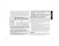
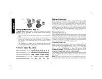
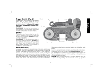
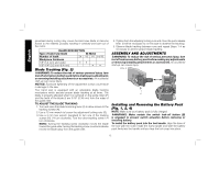
English generated during cutting may cause the band saw blade to become bound to the material, possibly resulting in overload and burn-out of the motor. BLADE DESCRIPTION Type of band saw blade Bi-Metal Number of teeth 24 18 14 14/18 Workpiece thickness 1/8" (3.2 mm) and under •• 1/8"-1/4" (3.2 mm-6.4 mm) •• Blade Tracking (Fig. 2) WARNING: To reduce the risk of serious personal injury, turn tool off and remove battery pack before making any adjustments or removing/installing attachments or accessories. An accidental start-up can cause injury. NOTICE: Excessive tightening of the adjustment screws could result in damage to the saw. Your band saw is equipped with an adjustable blade tracking mechanism which assures proper blade tracking at all times. The blade is properly adjusted when it is centered on the guide rollers (F) and the teeth of the blade (I) are 3/16" (0.38 mm) from the edge of the guide roller. TO ADJUST THE BLADE TRACKING 1. Turn and open the blade tensioning lever (H) to allow access to the tracking screws (N). 2. Use a 10 mm wrench to loosen the adjustment locking nuts (G). 3. Use a 3 mm hex wrench (supplied) to turn one of the tracking screws (N) 1/4 turn clockwise. Turn the other tracking screw 1/4 turn clockwise. NOTE: Turning the tracking screw clockwise moves the blade toward the guide roller, turning the tracking screw counterclockwise moves the blade away from the guide roller. 4. Tighten both the adjusting locking nuts and close the quick release lever. (It will be necessary to run the saw to observe the tracking.) 5. Observe blade tracking between runs and repeat Steps 1-4 as necessary to achieve proper blade tracking. ASSEMBLY AND ADJUSTMENTS WARNING: To reduce the risk of serious personal injury, turn tool off and remove battery pack before making any adjustments or removing/installing attachments or accessories. An accidental start-up can cause injury. FIG. 4 P Installing and Removing the Battery Pack (Fig. 1, 2, 4) NOTE: Make sure your battery pack is fully charged. WARNING: Make certain the switch lock-off button (B) is engaged to prevent switch actuation before removing or installing battery. To install the battery pack into the tool handle, align the base of the tool with the notch inside the tool's handle and slide the battery pack firmly into the handle until you hear the lock snap into place. 12
-
 1
1 -
2
-
3
-
4
-
5
-
6
-
7
-
8
-
 9
9 -
 10
10 -
 11
11 -
 12
12 -
 13
13 -
 14
14 -
 15
15 -
 16
16 -
 17
17 -
 18
18 -
 19
19 -
20
-
21
-
22
-
23
-
24
-
25
-
26
-
27
-
28
-
29
-
30
-
31
-
32
-
33
-
34
-
35
-
36
-
37
-
38
-
39
-
40
-
41
-
42
-
43
-
44
-
45
-
46
-
47
-
48
-
49
-
50
-
51
-
52
-
53
-
54
-
55
-
56
-
57
-
58
-
59
-
60
 |
 |
