Dewalt DW0822 Instruction Manual - Page 2
Field Calibration Check, Troubleshooting - laser
 |
View all Dewalt DW0822 manuals
Add to My Manuals
Save this manual to your list of manuals |
Page 2 highlights
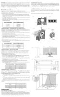
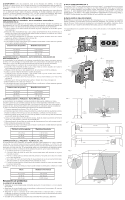
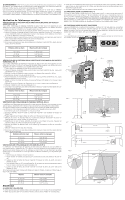
WARNING: Since accessories, other than those offered by DeWALT, have not been tested with this product, use of such accessories with this tool could be hazardous. To reduce the risk of injury, only DeWALT recommended accessories should be used with this product. Recommended accessories for use with your tool are available at extra cost from your local dealer or authorized service center. If you need assistance in locating any accessory, please contact DeWALT Industrial Tool Co., 701 East Joppa Road, Baltimore, MD 21286, call 1-800-4-DeWALT (1-800433-9258) or visit our website: www.DeWALT.com. Field Calibration Check CHECKING ACCURACY - HORIZONTAL BEAM, SCAN DIRECTION (FIG. 6) Checking the horizontal scan calibration of the laser requires two walls 30' (9 m) apart. It is important to conduct a calibration check using a distance no shorter than the distance of the applications for which the tool will be used. 1. Attach the laser to a wall using its pivot bracket. Make sure the laser is facing straight ahead. 2. Turn on the laser's horizontal beam and pivot the laser approximately 45˚ so that the right- most end of the laser line is striking the opposing wall at a distance of at least 30' (9 m). Mark the center of the beam (a). 3. Pivot the laser approximately 90˚ to bring the left-most end of the laser line around to the mark made in Step 2. Mark the center of the beam (b). 4. Measure the vertical distance between the marks. 5. If the measurement is greater than the values shown below, the laser must be serviced at an authorized service center. THE LASER BEAMS FLASH (FIG. 4) The DW0822 laser level has been designed to self-level up to 4° in all directions when positioned as shown in Figure 4. If the laser is tilted so much that internal mechanism cannot plumb itself, it will flash the laser-the tilt range has been exceeded. THE FLASHING BEAMS CREATED BY THE LASER ARE NOT LEVEL OR PLUMB AND SHOULD NOT BE USED FOR DETERMINING OR MARKING LEVEL OR PLUMB. Try repositioning the laser on a more level surface. THE LASER BEAMS WILL NOT STOP MOVING The DW0822 is a precision instrument. Therefore, if it is not positioned on a stable (and motionless) surface, the tool will continue to try to find plumb. If the beam will not stop moving, try placing the tool on a more stable surface. Also, try to make sure that the surface is relatively flat, so that the laser is stable. *Accuracy spec assumes laser is positioned on a surface within 4° of level. FIG. 1 J FIG. 2 Distance Between Walls Measurement Between Marks 15' (4.5 m) 30' (9 m) 50' (15 m) 1/16" (2 mm) 5/32" (4 mm) 1/4" (6 mm) CHECKING ACCURACY - HORIZONTAL BEAM, PITCH DIRECTION (FIG. 7) Checking the horizontal pitch calibration of the laser requires a single wall at least 30' (9 m) long. It is important to conduct a calibration check using a distance no shorter than thedistance of the applications for which the tool will be used. 1. Attach the laser to one end of a wall using its pivot bracket. 2. Turn on the laser's horizontal beam and pivot the laser toward the opposite end of the wall and approximately parallel to the adjacent wall. 3. Mark the center of the beam at two locations (c, d) at least 30' (9 m) apart. 4. Reposition the laser to the opposite end of the wall. 5. Turn on the laser's horizontal beam and pivot the laser back toward the first end of the wall and approximately parallel to the adjacent wall. 6. Adjust the height of the laser so that the center of the beam is aligned with the nearest mark (d). 7. Mark the center of the beam (e) directly above or below the farthest mark (c). 8. Measure the distance between these two marks (c, e). 9. If the measurement is greater than the values shown below, the laser must be serviced at an authorized service center. Distance Between Walls Measurement Between Marks 15' (4.5 m) 30' (9 m) 50' (15 m) 1/16" (2 mm) 5/32" (4 mm) 1/4" (6 mm) CHECKING ACCURACY - VERTICAL BEAM (FIG. 8) Checking the vertical (plumb) calibration of the laser can be most accurately done when there is a substantial amount of vertical height available, ideally 30' (9 m), with one person on the floor positioning the laser and another person near a ceiling to mark the position of the beam. It is important to conduct a calibration check using a distance no shorter than the distance of the applications for which the tool will be used. 1. Start by marking a 5' (1.5 m) line on the floor. 2. Turn on the laser's vertical beam and position the unit at one end of the line, facing the line. 3. Adjust the unit so its beam is aligned and centered on the line on the floor. 4. Mark the position of the laser beam on the ceiling (f). Mark the center of the laser beam directly over the midpoint of the line on the floor. 5. Reposition the laser at the other end of the line on the floor. Adjust the unit once again so its beam is aligned and centered on the line on the floor. 6. Mark the position of the laser beam on the ceiling (g), directly beside the first mark (f). 7. Measure the distance between these two marks. 8. If the measurement is greater than the values shown below, the laser must be serviced at an authorized service center. Distance Between Walls Measurement Between Marks 15' (4.5 m) 1/16" (2 mm) 30' (9 m) 5/32" (4 mm) 50' (15 m) 1/4" (6 mm) CHECKING ACCURACY - PLUMB (FIG. 5-6) Checking the plumb calibration of the laser can be most accurately done when there is a substantial amount of vertical height available, ideally 25' (7.5 m), with one person on the floor positioning the laser and another person near a ceiling to mark the dot created by the beam on the ceiling (Fig. 5). It is important to conduct a calibration check using a distance no shorter than the distance of the applications for which the tool will be used. 1. Start by marking a point on the floor. 2. Place the laser so that the down dot beam is centered on the point marked on the floor. 3. Allow time for the laser to settle to plumb and mark the center of the dot created by the up beam. 4. Turn the laser 180° as shown (Fig. 6), making sure that the down dot beam is still centered on the point previously marked on the floor. 5. Allow time for the laser to settle to plumb and mark the center of the dot created by the up beam. If the measurement between the two marks is greater than shown below, the laser is no longer in calibration. A B F FIG. 3 E D G FIG. 5 25' (7.5 m) FIFGIG. .77 StSetpep11,2, 2 cc StSetpep33 Step8 8 cc ee SStetepp77 FIFGIG. 8. 8 SStteepp 7 gg ff FIG. 4 J FLASHING CLIGNOTANT DESTELLA >4° FIG. 6 Step 2 Step 4 b Step 3 a Step 2 Step 3 Step 1 99mm ((3300')') dd StSetpep33 SStetepps44, ,55 d dd SteSptep6 6 SStetepp44 SStteepp66 gg ff Height Measurement Between Marks 15' (4.5 m) 1/8" (3 mm) 30' (9 m) 1/4" (6 mm) 50' (15 m) 11/32" (9 mm) Troubleshooting THE LASER DOES NOT TURN ON • Make sure batteries are installed according to (+), (-) markings on battery door. • Make sure the batteries are in proper working condition. If in doubt, try installing new batteries. • Make sure that the battery contacts are clean and free of rust or corrosion. Be sure to keep the laser level dry and use only new, high-quality batteries to reduce the chance of battery leakage. • If the laser has been stored in extremely hot temperatures, allow it to cool. SStetepp2s,23, 3 11..55 mm ((55'')) SStteepp11 SStep 5
-
 1
1 -
 2
2 -
 3
3 -
 4
4 -
 5
5 -
 6
6
 |
 |
