Dewalt DW716 Instruction Manual - Page 7
FOR INCREASED ACCURACY, Perpendicularity Adjustment, Parallel Adjustment, Kerf Adjustment - laser
 |
View all Dewalt DW716 manuals
Add to My Manuals
Save this manual to your list of manuals |
Page 7 highlights
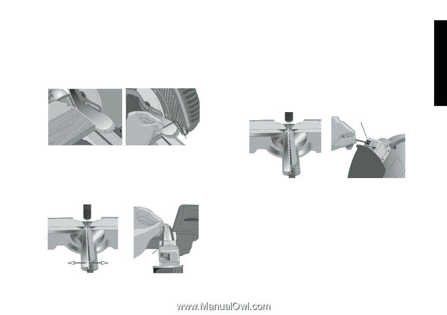
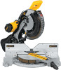
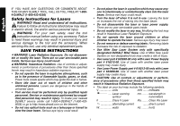
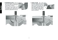
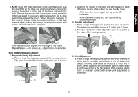
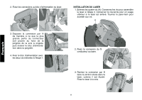
English 6. KERF: Lock the miter saw head in the DOWN position. Lay the board flat on the table and against the fence aligning the edge of the board to either side of the blade (shown to the left). Through the access hole in the lower guard, rotate the miter saw guard if necessary, adjust side screw (G) to align laser to the edge of the board. When adjusting the laser to the right of blade, apply a continuous force to the hex wrench while making adjustment to maintain contact with screw until adjustment is complete. b. Observe the motion of the laser line with respect to edge of framing square while pulling the saw handle down. If the laser line moves right, turn top screw (E) clockwise. If the laser line moves left, turn top screw (E) counterclockwise. 8. Parallel Adjustment a. Place a large framing square against the fence as shown. The miter saw should be locked at 0˚ miter and 0˚ bevel. b. Turn the front screw (F) to adjust the laser line parallel to the edge of the framing square. F G The laser should be aligned with the edge of the board. Repeat Steps 4-6 to ensure ALL adjustments are accurate. FOR INCREASED ACCURACY: 7. Perpendicularity Adjustment a. Place a large framing square against the fence as shown. The miter saw should be locked at 0˚ miter and 0˚ bevel. E L R 9. Kerf Adjustment a. Place a large framing square against the fence oriented to either side of the blade teeth (shown to the left side of the blade). The miter saw should be locked at 0˚ miter and 0˚ bevel. When adjusting the laser to the right of blade, apply a continuous force to the hex wrench while making adjustment to maintain contact with screw until adjustment is complete. 6
-
 1
1 -
 2
2 -
 3
3 -
 4
4 -
 5
5 -
 6
6 -
 7
7 -
 8
8 -
 9
9 -
 10
10 -
 11
11 -
 12
12 -
13
-
14
-
15
-
16
-
17
-
18
-
19
-
20
-
21
-
22
-
23
-
24
-
25
-
26
-
27
-
28
 |
 |