Dewalt DW802G Instruction Manual - Page 13
Mounting Cutting Wheels, Using Cutting Wheels, Mounting Closed Type 1 Guard
 |
View all Dewalt DW802G manuals
Add to My Manuals
Save this manual to your list of manuals |
Page 13 highlights
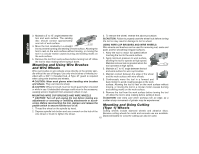
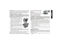
WARNING: A closed, 2-sided cutting wheel guard is not included loose, tighten the adjusting screw (M) with this tool but is required when using cutting wheels. Failure to with the clamp lever in the closed use proper flange and guard can result in injury resulting from wheel position. English breakage and wheel contact. See page 7 for more information. CAUTION: Do not tighten adjust- ing screw with clamp lever in open MOUNTING CLOSED (TYPE 1) GUARD position. Undetectable damage to M CAUTION: Turn off and unplug the tool before making any guard or mounting hub may result. adjustments or removing or installing attachments or acces- sories. Before reconnecting the tool, depress and release the paddle switch to ensure that the tool is off. 1. Open the guard latch (J), and align the J arrow on the guard (K) with the arrow on the hub (L). This will align the lugs with slots on the gear case cover. Position the guard facing backward. 2. Push the guard down until the guard lug L engages and rotates freely in the groove on the gear case hub. K 3. Rotate guard (I) into desired working MOUNTING CUTTING WHEELS CAUTION: Turn off and unplug the tool before making any adjustments or removing or installing attachments or accessories. Before reconnecting the tool, depress and release the paddle switch to ensure that the tool is off. CAUTION: Matching diameter threaded backing flange and clamp nut (included with tool) must be used for cutting wheels. 1. Place the unthreaded backing flange on spindle with the raised section (pilot) facing up. The raised section (pilot) on the backing flange will be against the wheel when the wheel is installed. 2. Place the wheel on the backing flange, centering the wheel on the raised section (pilot). position. The guard body should be positioned between the spindle and the operator to provide maximum operator protection. 3. Install the threaded clamp nut with the raised section (pilot) facing away from the wheel. 4. Depress the spindle lock button and tighten clamp nut with a wrench. 4. Close the guard latch to secure the guard on the gear case cover. You I 5. To remove the wheel, grasp and turn while depressing the spindle lock button. should be unable to rotate the guard by hand when the latch is in closed position. Do not operate grinder with a loose guard or clamp lever in open position. 5. To remove the guard, open the guard latch, rotate the guard so USING CUTTING WHEELS WARNING: Do not use edge grinding/cutting wheels for surface grinding applications because these wheels are not designed for side pressures encountered with surface grinding. Wheel breakage that the arrows are aligned and pull up on the guard. and injury may result. NOTE: The guard is pre-adjusted to the diameter of the gear case 1. Allow tool to reach full speed before touching tool to work hub at the factory. If, after a period of time, the guard becomes surface. 11
-
 1
1 -
2
-
3
-
4
-
5
-
6
-
7
-
 8
8 -
 9
9 -
 10
10 -
 11
11 -
 12
12 -
 13
13 -
 14
14 -
 15
15 -
 16
16 -
 17
17 -
 18
18 -
19
-
20
-
21
-
22
-
23
-
24
-
25
-
26
-
27
-
28
-
29
-
30
-
31
-
32
-
33
-
34
-
35
-
36
-
37
-
38
-
39
-
40
-
41
-
42
-
43
-
44
-
45
-
46
-
47
-
48
 |
 |
