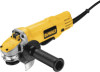
Dewalt DWE4120 Instruction Manual - Page 13
OPERATION, Guards and Flanges, Switches - grinder
 |
View all Dewalt DWE4120 manuals
Add to My Manuals
Save this manual to your list of manuals |
Page 13 highlights
English from your local dealer or authorized service center. Grinding and cutting with wheels other than Type 27 and 29 require different accessory guards not included with tool. A Type 1 guard is provided for use with the Type 1 wheel. Mounting instructions for accessory guards are shown below and are also included in the accessory package. MOUNTING AND REMOVING (TYPE 27) ONE-TOUCH™ GUARD (FIG. 4, 5) FIG. 4 NOTE: If your grinder is supplied with a keyless ONE TOUCH™ guard, ensure the N screw, lever and spring are fitted correctly L before mounting the guard. 1. Press the guard release lever (K). 2. While holding the guard release lever open, M align the lugs (L) on the guard with the slots on the gear case (M). K 3. Keeping the guard release lever open, push the guard down until the guard lugs engage and rotate them in the groove on the gear case hub. Release the guard release lever. 6. To remove the guard, follow steps 1-3 of these instructions in reverse. NOTE: Edge grinding and cutting can be performed with Type 27 wheels designed and specified for this purpose; 1/4" (6.35 mm) thick wheels are designed for surface grinding while 1/8" (3.17 mm) wheels are designed for edge grinding. Cutting can also be performed by using a Type 1 wheel and a Type 1 guard. OPERATION WARNING: To reduce the risk of injury, turn unit off and disconnect it from power source before installing and removing accessories, before adjusting or when making repairs. An accidental start-up can cause injury. Guards and Flanges It is important to choose the correct guards and flanges to use with the grinder accessories. See page 9-10 and this page for the correct accessories. NOTE: Edge grinding and cutting can be performed with Type 27 wheels designed and specified for this purpose. 4. With the spindle facing the operator, rotate FIG. 5 the guard clockwise into the desired working position. The guard body should be positioned between the spindle and the operator to provide maximum operator protection. 5. For easy adjustment, the guard can be rotated in the clockwise direction. NOTE: The guard release lever should snap into one of the alignment holes (N) on the guard collar. This insures that the guard is secure. The guard can be repositioned the opposite direction by depressing the guard release lever. WARNING: Accessories must be rated for at least the speed recommended on the tool warning label. Wheels and other accessories running over rated accessory speed may burst and cause injury. Every unthreaded accessory must have a 7/8" arbor hole. If it does not, it may have been designed for a circular saw and should not be used. Use only the accessories shown on pages 9-10. Accessory ratings must be above listed minimum wheel speed as shown on tool nameplate. Switches CAUTION: Hold the side handle and body of the tool firmly to maintain control of the tool at start up and during use and until the wheel or accessory stops rotating. Make sure the wheel has come to a complete stop before laying the tool down. 11
-
 1
1 -
2
-
3
-
4
-
5
-
6
-
7
-
 8
8 -
 9
9 -
 10
10 -
 11
11 -
 12
12 -
 13
13 -
 14
14 -
 15
15 -
 16
16 -
 17
17 -
 18
18 -
19
-
20
-
21
-
22
-
23
-
24
-
25
-
26
-
27
-
28
-
29
-
30
-
31
-
32
-
33
-
34
-
35
-
36
-
37
-
38
-
39
-
40
-
41
-
42
-
43
-
44
-
45
-
46
-
47
-
48
-
49
-
50
-
51
-
52
-
53
-
54
-
55
-
56
-
57
-
58
-
59
-
60
-
61
-
62
-
63
-
64
-
65
-
66
-
67
-
68
 |
 |
