Dewalt DWE46102 Instruction Manual - Page 10
Motor, Components Fig. 1, Assembly And Adjustments - grinder
 |
View all Dewalt DWE46102 manuals
Add to My Manuals
Save this manual to your list of manuals |
Page 10 highlights
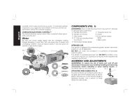
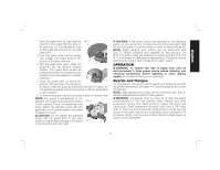
English overload current value (motor burn-up point). If continued overload shutdowns occur, apply less force/weight on the tool until the tool will function without the overload engaging. COMPLETE ELECTRONIC CONTROL™ The internal electronic speed control offers consistent wheel speed while using the tool. Motor Be sure your power supply agrees with the nameplate marking. Voltage decrease of more than 10% will cause loss of power and overheating. DEWALT tools are factory tested; if this tool does not operate, check power supply. FIG. 1 H C I A N E F G COMPONENTS (FIG. 1) WARNING: Never modify the power tool or any part of it. Damage or personal injury could result. A. Spindle lock button F. Threaded clamp nut B. Spindle (not shown) G. Guard C. Side handle H. Dust ejection system D. 6" (150 mm) grinding wheel (DES) (not shown) I. Slider switch E. Anti-lockup backing flange INTENDED USE This grinder is designed for professional grinder, sander, wire brush, polisher or cut-off application. DO NOT use under wet conditions or in presence of flammable liquids or gases. This grinder is a professional power tool. DO NOT let children come into contact with the tool. Supervision is required when inexperienced operators use this tool. ASSEMBLY AND ADJUSTMENTS WARNING: To reduce the risk of injury, turn unit off and disconnect it from power source before installing and removing accessories, before adjusting or when making repairs. An accidental start-up can cause injury. FIG. 2 ATTACHING SIDE HANDLE (FIG. 2) C The side handle (C) can be fitted to either side of the gear case in the threaded holes, as shown. Before using the tool, check that the handle is tightened securely. Use a wrench to firmly tighten the side handle. 8
-
 1
1 -
2
-
3
-
4
-
 5
5 -
 6
6 -
 7
7 -
 8
8 -
 9
9 -
 10
10 -
 11
11 -
 12
12 -
 13
13 -
 14
14 -
 15
15 -
16
-
17
-
18
-
19
-
20
-
21
-
22
-
23
-
24
-
25
-
26
-
27
-
28
-
29
-
30
-
31
-
32
-
33
-
34
-
35
-
36
-
37
-
38
-
39
-
40
-
41
-
42
-
43
-
44
-
45
-
46
-
47
-
48
-
49
-
50
-
51
-
52
-
53
-
54
-
55
-
56
-
57
-
58
-
59
-
60
-
61
-
62
-
63
-
64
-
65
-
66
 |
 |
