Dewalt DWE46102 Instruction Manual - Page 11
Rotating the Gear Case FIg. 3, Accessories
 |
View all Dewalt DWE46102 manuals
Add to My Manuals
Save this manual to your list of manuals |
Page 11 highlights
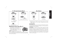
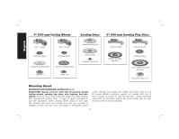
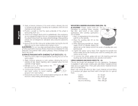
6" (150 mm) Grinding Wheels Wire Wheels English Type 27 guard Type 27 guard Type 27 guard Type 27 guard backing flange Type 27 hubbed wheel 3" wire cup brush 4" wire wheel Type 27 depressed center wheel 3. Reinstall screws to attach the gear case to the motor housing. Tighten screws to 20 in.-lbs. torque. Overtightening could cause screws to strip. threaded clamp nut Rotating the Gear Case (FIg. 3) 1. Removethefourcornerscrewsattaching FIG. 3 the gear case to motor housing. 2. Without separating the gear case from motor housing, rotate the gear case head to desired position. NOTE: If the gear case and motor housing 90˚ become separated by more than 1/8" 90˚ (3.17 mm), the tool must be serviced and re-assembled by a DEWALT service center. Failure to have the tool serviced may cause brush, motor and bearing failure. Accessories It is important to choose the correct guards, backing pads and flanges to use with grinder accessories. See pages 9-10 for information on choosing the correct accessories. WARNING: Accessories must be rated for at least the speed recommended on the tool warning label. Wheels and other accessories running over rated accessory speed may burst and cause injury. Threaded accessories must have a 5/8"-11 hub. Every unthreaded accessory must have a 7/8" arbor hole. If it does not, it may have been designed for a circular saw and should not be used. Use only the accessories shown on pages 9-10 of this manual. Accessory ratings must be above listed minimum wheel speed as shown on tool nameplate. 9
-
 1
1 -
2
-
3
-
4
-
5
-
 6
6 -
 7
7 -
 8
8 -
 9
9 -
 10
10 -
 11
11 -
 12
12 -
 13
13 -
 14
14 -
 15
15 -
 16
16 -
17
-
18
-
19
-
20
-
21
-
22
-
23
-
24
-
25
-
26
-
27
-
28
-
29
-
30
-
31
-
32
-
33
-
34
-
35
-
36
-
37
-
38
-
39
-
40
-
41
-
42
-
43
-
44
-
45
-
46
-
47
-
48
-
49
-
50
-
51
-
52
-
53
-
54
-
55
-
56
-
57
-
58
-
59
-
60
-
61
-
62
-
63
-
64
-
65
-
66
 |
 |
