Dewalt DWFP55120 Instruction Manual - Page 9
Assembly - compressor parts
 |
View all Dewalt DWFP55120 manuals
Add to My Manuals
Save this manual to your list of manuals |
Page 9 highlights
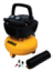
English When the air compressor is operating, the check valve (G) is open, allowing compressed air to enter the air tank. When the air compressor reaches cut-out pressure, the check valve closes, allowing air pressure to remain inside the air tank. TANK PRESSURE GAUGE G C B D The tank pressure gauge (B) indicates the reserve air pressure in the tank. OUTLET PRESSURE GAUGE The outlet pressure gauge (C) indicates the air pressure available at the outlet side of the regulator. This pressure is controlled by the regulator and is always less than or equal to the tank pressure. REGULATOR The regulator (D) controls the air pressure shown on the outlet pressure gauge. Turn regulator knob clockwise to increase pressure and counterclockwise to decrease pressure. DRAIN VALVE The drain valve (F) is located at the base of the air H tank and is used to drain condensation at the end of each use. See Draining Air Tank under Maintenance. F COOLING SYSTEM This compressor contains an advanced design cooling system. It is normal for this fan to blow air through the vent holes in large amounts. The cooling system is working when air is expelled. AIR COMPRESSOR PUMP The pump compresses air into the air tank. Working air is not available until the compressor has raised the air tank pressure above that required at the air outlet. MOTOR OVERLOAD PROTECTOR (NOT SHOWN) The motor has thermal overload protector. If the motor overheats for any reason, the overload protector will shut off the motor. The motor must be allowed to cool down before restarting. TO RESTART: 1. Set the on/off switch to "O" and unplug unit. 2. Allow the motor to cool. 3. Plug the power cord into the correct branch circuit receptacle. 4. Set the on/off switch to "I" position. ASSEMBLY CONTENTS OF CARTON 1 - Air Compressor 1 - Air Hose 1 - Female Tire Chuck 1 - Inflator Accessory Kit TOOLS REQUIRED FOR ASSEMBLY 1 - Adjustable wrench UNPACKING Remove unit from carton and discard all packaging. NOTE: Save all parts bags. ASSEMBLE HOSE 1. Ensure regulated pressure guage reads 0 psi. 2. Assemble hose to air outlet. (H) 9
-
 1
1 -
2
-
3
-
 4
4 -
 5
5 -
 6
6 -
 7
7 -
 8
8 -
 9
9 -
 10
10 -
 11
11 -
 12
12 -
 13
13 -
 14
14 -
15
-
16
-
17
-
18
-
19
-
20
-
21
-
22
-
23
-
24
-
25
-
26
-
27
-
28
-
29
-
30
-
31
-
32
-
33
-
34
-
35
-
36
-
37
-
38
-
39
-
40
-
41
-
42
-
43
-
44
-
45
-
46
-
47
-
48
-
49
-
50
-
51
-
52
-
53
-
54
-
55
 |
 |
