Dewalt DWMT70779 Instruction Manual - Page 6
Features - siphon spray gun
 |
View all Dewalt DWMT70779 manuals
Add to My Manuals
Save this manual to your list of manuals |
Page 6 highlights
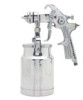
English FEATURES D SPRAY GUN BODY The multi-purpose body of the spray gun has a conventional siphon design. MATERIAL CUP The cam style cup (E) of the spray gun can hold 32oz (1000 cc). The cup is easily removed from the spray gun E body by pushing the material cup release tab (D). MATERIAL FILTER The material filter (C) is used A to protect against contaminants and small particles.It is located inside of the spray gun, B between the material cup (E) and air cap (A). AIR CAP HORNS The position of the air cap (A) horns (B) allow two spray patterns. Horizontal position Vertical position FLUID CONTROL KNOB The fluid control knob (J) K allows control of the material amount released (the density of the "fan spray"). AIR VOLUME CONTROL KNOB The air volume control knob (H) controls the air flow and allows for a MAX of 40 PSI to reduce over-spray and efficient air consumption. J H I PATTERN CONTROL KNOB The pattern control knob (I) allows the width of the "fan spray" to be adjusted. FIXED HOOK The spray gun includes a fixed hook (K) on the body to allow for convenient hanging when stored. AIR INLET The tool's air inlet (G) located at the bottom of the handle is used for connecting an air supply with a standard 1/4" NPT American thread. G 6
-
 1
1 -
 2
2 -
 3
3 -
 4
4 -
 5
5 -
 6
6 -
 7
7 -
 8
8 -
 9
9 -
 10
10 -
 11
11 -
 12
12 -
13
-
14
-
15
-
16
-
17
-
18
-
19
-
20
-
21
-
22
-
23
-
24
-
25
-
26
-
27
-
28
-
29
-
30
-
31
-
32
-
33
-
34
-
35
-
36
 |
 |
