Dewalt DWX724 Instruction Manual - Page 7
Carry Strap
 |
View all Dewalt DWX724 manuals
Add to My Manuals
Save this manual to your list of manuals |
Page 7 highlights
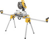
English 3. When the front edge of beam and locator clip are engaged, a slight downward pivot will allow secure engagement of the release levers to the back of the beam. Follow same procedure with second mounting bracket at the appropriate position on the beam for the size of the plywood. 4. Place plywood onto mounting brackets and align drilled holes with slots in mounting brackets. Refer to DW7231 Hardware Selection Chart and use either Method 1 or 2 to secure plywood to mounting brackets. 5. Use 1/2" (13 mm) wrench to tighten hardware. 6. The miter saw should be mounted to plywood using holes in the miter saw base. The hardware size will be determined by the holes in the miter saw base. Hardware should be 1-1/4" (31.8 mm) longer than the maximum height of the miter saw base at each mounting location. FIG. 8 WIDTH OF SAW + 4" (101.6 mm) 1" (25.5 mm) 1" (25.5 mm) MINIMUM OF 16" (406.4 mm) MUST BE AT 15" LEAST AS DEEP((381 mm) AS THE SAW BOTH BEING MOUNT- SIDES ING MOUNT MITER SAW IN SHADED AREA a. Transfer location of mounting holes from miter saw base to plywood. b. Drill holes accordingly to the size of the hardware chosen. NOTE: Hardware must be purchased to mount miter saw to plywood. All purchased hardware should be a minimum of Grade 5 or Class 8.8. c. Secure miter saw to plywood as shown in Figure 9. Saw base (P), 3/4" (19 mm) plywood (T), flat washer (Q), lock washer (S) and nut (R). NOTE: Ensure a flat washer (Q) is used between plywood (T) and lock washer (S). d. Tighten all hardware. Carry Strap If you purchase the carry strap accessory for DEWALT stands, use the square hole in the metal end to mount the accessory. FIG. 9 3/8" (9.5 mm) DIAMETER P HOLES, ALL 4 CORNERS 2" (50.8 mm) MINIMUM BOTH SIDES T S Q R 1" (25.5 mm) 1" (25.5 mm) 5
-
 1
1 -
 2
2 -
 3
3 -
 4
4 -
 5
5 -
 6
6 -
 7
7 -
 8
8 -
 9
9 -
 10
10 -
 11
11 -
 12
12 -
13
-
14
-
15
-
16
-
17
-
18
-
19
-
20
-
21
-
22
-
23
-
24
-
25
-
26
-
27
-
28
-
29
-
30
-
31
-
32
 |
 |
