Dewalt DWX725B Instruction Manual - Page 4
ASSEMBLY, Transport Latch Fig. 3, Mounting A Sacrificial Wood Surface, Fig. 4 - saw stand
 |
View all Dewalt DWX725B manuals
Add to My Manuals
Save this manual to your list of manuals |
Page 4 highlights
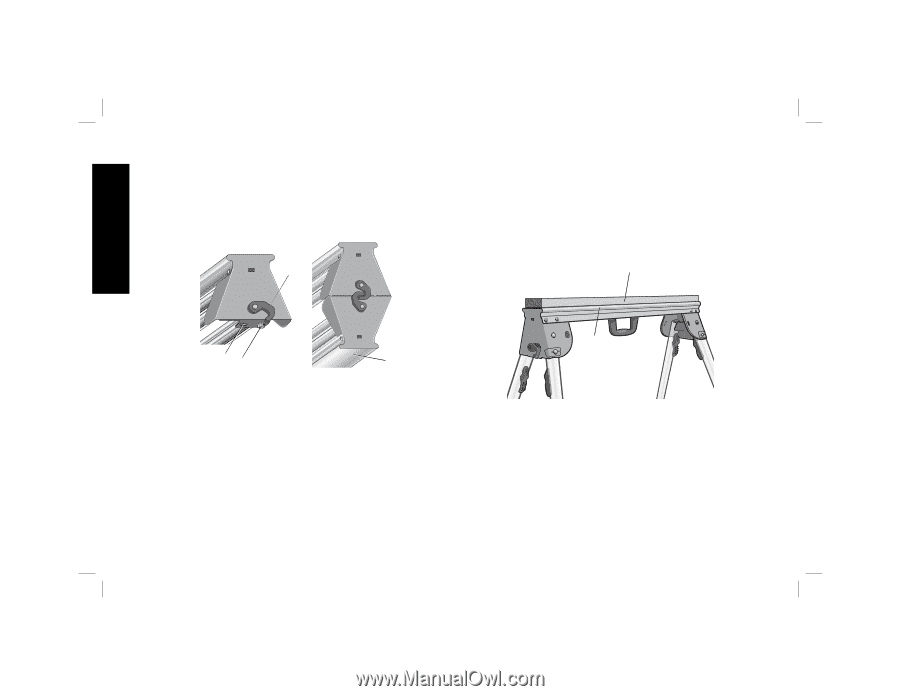
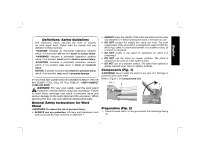
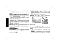
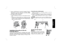
English 2. Depress the leg lock lever (D) or release button (C) and pull leg up until the locking pin clicks into place. Repeat on each leg. 3. Lift the stand by the center beam and place it in an upright position. The stand should be stable and should not rock. NOTE: Ensure all locking pins are engaged and the legs are locked in place. FIG. 3 E 2. Rotate the transport latches (E) clockwise simultaneously until they latch together. Repeat on other side. Ensure the two work stands are mated properly, as shown. 3. To release the transport latch: a. Place the stands on the ground with one beam facing down. b. Apply pressure to the tip of each transport latch hook until they move in a counterclockwise direction. Once the tips are forced past each other the latches will snap open. FIG. 4 H A GF A ASSEMBLY Transport Latch (Fig. 3) The transport latch (E) was designed to aid in carrying two work stands at the same time by lashing two work stands together for transport. 1. Place one stand on the ground with the beam (A) facing down. Place the second stand onto the first stand with the beam facing up. NOTE: Rotate stands to ensure locator feet (F) and holes (G) align to connect stands. Mounting A Sacrificial Wood Surface (Fig. 4) The DWX725 work stand allows a 2 x 4 to be mounted in the top channel of the beam (A) as a sacrificial element when needed. This can be useful if working with a material that could get scratched by the main beam or when using a circular saw to cut material. 2
-
 1
1 -
 2
2 -
 3
3 -
 4
4 -
 5
5 -
 6
6 -
 7
7 -
 8
8 -
 9
9 -
 10
10 -
11
-
12
-
13
-
14
-
15
-
16
-
17
-
18
-
19
 |
 |