Dewalt DXCMPA1982054 Instruction Manual - Page 11
Assembly Fig. 1, Compatibility, Location - power tools
 |
View all Dewalt DXCMPA1982054 manuals
Add to My Manuals
Save this manual to your list of manuals |
Page 11 highlights
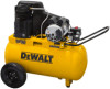
English 4. Plug the power cord into the correct branch circuit receptacle. 5. Set the Auto/Off switch to AUTO (-). INSTALLATION Assembly (Fig. 1) Unpack the air compressor. Inspect the unit for damage. If the unit has been damaged in transit, contact the carrier and complete a damage claim. Do this immediately because there are time limitations to damage claims. The carton should contain: • air compressor • operator and parts manuals Check the compressor's serial label to ensure that you have received the model ordered, and that it has the required pressure rating for its intended use. INSTALLING HANDLE 1. Insert end of handle (N) into the base. N 2. Tighten the bolts (O)(provided) against the base. INSTALLING HOSES WARNING: Risk of unsafe operation. Firmly O grasp hose in hand when installing or disconnecting to prevent hose whip. 1. Ensure regulated pressure gauge reads 0 psi. 2. Apply sealant tape to hose threads. 3. Assemble hose to air outlet (F). IMPORTANT: Do not assemble splitters directly to the air outlet (F). NOTE: Assembling quick connect bodies (L) to air outlet (F) and quick connect plugs to hose ends make connecting and disconnecting hoses simple and easy. Quick connect bodies and plugs are available for purchase from your local dealer or authorized service center. DISCONNECTING HOSES WARNING: Risk of unsafe operation. Firmly grasp hose in hand when installing or disconnecting to prevent hose whip. 1. Ensure regulated pressure gauge reads 0 psi. 2. Remove hose from air outlet (F). Lubrication and Oil AIR COMPRESSOR The air compressor pump was filled WITH oil at the manufacturer. Check air compressor pump oil level before operating unit. See Compressor Pump Oil under Maintenance. Compatibility Air tools and accessories that are run off the compressor must be compatible with petroleum based products. If you suspect that a material is not compatible with petroleum products, an air line filter for removal of moisture and oil vapor in compressed air is required. NOTE: Always use an air line filter to remove moisture and oil vapor when spraying paint. Location • Locate the air compressor in a clean, dry, and well ventilated area. • Located the air compressor at least 12" (30.5 cm) away from the wall or other obstructions that will interfere with the flow of air. 11
-
 1
1 -
2
-
3
-
4
-
5
-
 6
6 -
 7
7 -
 8
8 -
 9
9 -
 10
10 -
 11
11 -
 12
12 -
 13
13 -
 14
14 -
 15
15 -
 16
16 -
17
-
18
-
19
-
20
-
21
-
22
-
23
-
24
-
25
-
26
-
27
-
28
-
29
-
30
-
31
-
32
-
33
-
34
-
35
-
36
-
37
-
38
-
39
-
40
-
41
-
42
-
43
-
44
-
45
-
46
-
47
-
48
-
49
-
50
-
51
-
52
-
53
-
54
-
55
-
56
-
57
-
58
-
59
-
60
-
61
-
62
-
63
-
64
-
65
-
66
-
67
-
68
-
69
-
70
-
71
-
72
-
73
-
74
-
75
-
76
-
77
-
78
-
79
-
80
-
81
-
82
-
83
-
84
-
85
-
86
-
87
-
88
-
89
-
90
-
91
-
92
 |
 |
