Dewalt DXGNR4000 Instruction Manual - Page 11
Operation
 |
View all Dewalt DXGNR4000 manuals
Add to My Manuals
Save this manual to your list of manuals |
Page 11 highlights
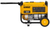
Operation Know the Generator Carefully read the Instruction Manual and Safety Rules before operating the generator. Save this manual for future reference. Become familiar with locations of all components. 1. 120 Volt AC, 20 Amp Duplex Outlets - Supplies electrical power for the operation of 120 Volt AC, 20 Amp, singlephase, 60 Hz, electrical lighting, appliance, tool and motor loads (NEMA 5-20R). 2. 120 Volt AC, 30 Amp Locking Receptacle - Supplies electrical power for operation of 120 Volt AC, 30 Amp, single-phase, 60 Hz, electrical lighting, appliance, tool and motor loads (NEMA L5-30R). 3. Circuit Breakers (AC) - Push-to-reset circuit breakers protect the generator against electrical overload. 4. Oil Drain - Use to drain engine oil. 5. Air Filter - Filters intake air as it is drawn into the engine. 6. Choke Lever - Used when starting a cold engine. 7. Fuel Tank - See Product Specifications for tank capacity. 8. Grounding Lug - Ground the generator to an approved earth ground here. See Grounding Generator If Used as Portable for details. 9. Run/Stop Switch - Must be in Run position to start manually. 10. Muffler - Quiets the engine. 11. Handle - Pivot and retract for storage. Press the spring- loaded button to move handle. 12. Fuel Cap - Fuel fill location. 13. Oil Fill - Add and check oil here. 14. Recoil Starter - Use to start engine manually. 15. Fuel Shut Off - Valve between fuel tank and carburetor. NOTICE: Operate unit on level ground for runtime meter accuracy. 16. Hour Meter - Tracks hours of operation for scheduled maintenance. 17. CO Protect - Carbon monoxide automatic shut down. 16 1 2 9 3 009103 3 6 5 15 11 14 17 7 13 4 009124 12 10 8 009125 Hour Meter The Hour Meter tracks hours of operation for scheduled maintenance. • The CHG OIL display will illuminate every 100 hours. The message will flash one hour before and one hour after each 100 hour interval, providing a two hour window to perform service. • The SVC display will illuminate every 100 hours. The mes- sage will flash one hour before and one hour after each 200 hour interval providing a two hour window to perform service. When the hour meter is in flash alert mode, the maintenance message will alternate with elapsed time in hours and tenths. The hours will flash four times, then alternate with the maintenance message four times until the meter automatically resets. • 100 hours - CHG OIL - Oil Change Interval (Every 100 hrs) • 200 hours - SVC - Service Air Filter (Every 200 hrs) NOTICE: The hour glass icon will flash when the engine is running. This signifies the meter is recording hours of operation. Owner's Manual for Portable Generator 9
-
 1
1 -
2
-
3
-
4
-
5
-
 6
6 -
 7
7 -
 8
8 -
 9
9 -
 10
10 -
 11
11 -
 12
12 -
 13
13 -
 14
14 -
 15
15 -
 16
16 -
17
-
18
-
19
-
20
-
21
-
22
-
23
-
24
 |
 |
