Dynex DX-ESW8 User Manual (English) - Page 3
Setting up the switch, Identifying switch components - cable
 |
UPC - 600603103872
View all Dynex DX-ESW8 manuals
Add to My Manuals
Save this manual to your list of manuals |
Page 3 highlights
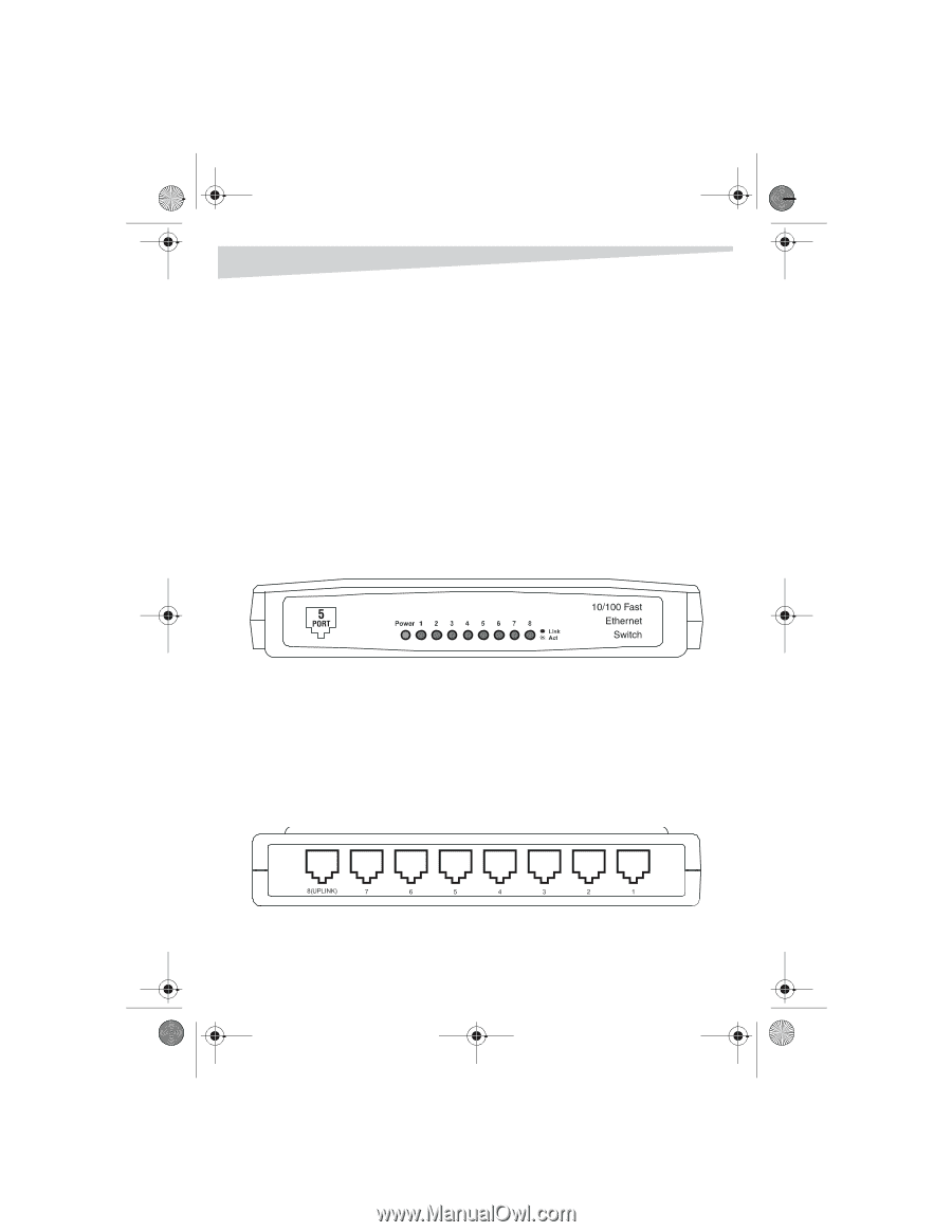
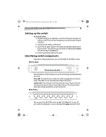
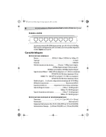
DX-ESW5-ESW8.fm Page 3 Friday, April 29, 2005 4:25 PM Dynex DX-ESW5 and DX-ESW8 Ethernet Switches 3 Setting up the switch To set up the switch: 1 Place the switch flat on a tabletop or use the enclosed screws to hang it vertically on a wall. Be sure to leave enough space around the switch for good ventilation. 2 Don't place heavy objects on the switch. 3 Connect the AC power adapter to the switch, then plug the adapter into an AC power outlet. The switch turns on and initializes by blinking the Link/Act LEDs and turning on the Power LED. 4 Connect your network cables to the switch. Identifying switch components Although the following illustrations show the DX-ESW8, the DX-ESW5 is similar. FRONT PANEL The LED indicators on the front panel are used for monitoring and troubleshooting the switch. Power LED: This indicator turns on when the switch is plugged into an AC power outlet. If the LED is not on, check the power adapter connections. Link/Act LEDs: These indicators show link and activity status. The port's LED indicator turns green when a device is connected to that port. The indicator flashes when data is being transmitted or received on the port. REAR PANEL The rear panel of the DX-ESW8 consists of eight 10/100 Mbps RJ- 45 ports. All ports can be the uplink port, so you can disregard the Uplink mark under Port 8.
-
 1
1 -
 2
2 -
 3
3 -
 4
4 -
 5
5 -
 6
6 -
 7
7 -
 8
8 -
 9
9 -
10
-
11
-
12
-
13
-
14
 |
 |