Dynex DX-PD510 User Manual (English) - Page 7
E. Controls, Indicators, and Connectors, - remote
 |
UPC - 600603101496
View all Dynex DX-PD510 manuals
Add to My Manuals
Save this manual to your list of manuals |
Page 7 highlights
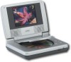
E. Controls, Indicators, and Connectors 1. Unit View (Refer to Figure 2) Figure 2 1) LCD Panel Shut Off Switch 2) Stop Button 3) Previous Button 4) Play Button 5) Next Button 6) Display Button 7) Open Button 8) Close Button 9) Brightness Up/Down Control 10) Volume Up/Down Control 11) Headphone Jack 1 12) Headphone Jack 2 13) DC 9V Input 14) Power On/Off Switch 15) Power LED 16) Remote Control Sensor 17) AV In Jack 18) AV Out Jack 7 PDF created with FinePrint pdfFactory Pro trial version http://www.fineprint.com
-
 1
1 -
 2
2 -
 3
3 -
 4
4 -
 5
5 -
 6
6 -
 7
7 -
 8
8 -
 9
9 -
 10
10 -
 11
11 -
 12
12 -
13
-
14
-
15
-
16
-
17
-
18
-
19
-
20
-
21
-
22
-
23
-
24
-
25
-
26
-
27
-
28
-
29
 |
 |

7
E. Controls, Indicators, and Connectors
1. Unit View
(Refer to Figure 2)
Figure 2
1) LCD Panel Shut Off Switch
15) Power LED
2) Stop Button
16) Remote Control Sensor
3) Previous Button
17) AV In Jack
4) Play Button
18) AV Out Jack
5) Next Button
6) Display Button
7) Open Button
8) Close Button
9) Brightness Up/Down Control
10) Volume Up/Down Control
11) Headphone Jack 1
12) Headphone Jack 2
13) DC 9V Input
14) Power On/Off Switch
PDF created with FinePrint pdfFactory Pro trial version