EMC DS-5100B Hardware Reference - Page 30
LED locations,
 |
View all EMC DS-5100B manuals
Add to My Manuals
Save this manual to your list of manuals |
Page 30 highlights
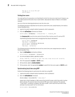
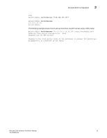
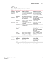
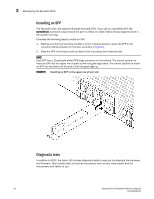
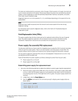
3 LED activity interpretation LED locations Figure 4 shows the locations of the port side LEDs on the Brocade 5100. 1 0 123 4 567 8 9 10 11 12 13 14 15 16 17 18 19 20 21 22 23 24 25 26 27 28 29 30 31 32 33 34 35 36 37 38 39 3 8 9 10 11 2 12 13 14 15 FIGURE 4 Brocade 5100 port side LEDs 1 System status LED (top) and System power (bottom) 2 Ethernet port Status LEDs (green/amber) 3 FC port status (port 9) Figure 5 shows the non-port side LEDs on the Brocade 5100. 1 2 FIGURE 5 Brocade 5100 non-port side LEDs 1 Power supply status LED 2 Power supply status LED 18 Brocade 5100 Hardware Reference Manual 53-1000854-02
-
 1
1 -
2
-
3
-
4
-
5
-
6
-
7
-
8
-
9
-
10
-
11
-
12
-
13
-
14
-
15
-
16
-
17
-
18
-
19
-
20
-
21
-
22
-
23
-
24
-
 25
25 -
 26
26 -
 27
27 -
 28
28 -
 29
29 -
 30
30 -
 31
31 -
 32
32 -
 33
33 -
 34
34 -
 35
35 -
36
-
37
-
38
-
39
-
40
-
41
-
42
-
43
-
44
-
45
-
46
-
47
-
48
-
49
-
50
-
51
-
52
-
53
-
54
 |
 |

18
Brocade 5100 Hardware Reference Manual
53-1000854-02
LED activity interpretation
3
LED locations
Figure 4
shows the locations of the port side LEDs on the Brocade 5100.
FIGURE 4
Brocade 5100 port side LEDs
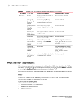
Figure 5
shows the non-port side LEDs on the Brocade 5100.
FIGURE 5
Brocade 5100 non-port side LEDs
8
9
10
11
12
13
14
15
0
1
2
3
8
9
10
11
16
17
18
19
24
25
26
27
32
33
34
35
4
5
6
7
12
13
14
15
20
21
22
23
28
29
30
31
36
37
38
39
1
2
3
1
System status LED (top) and System power (bottom)
2
Ethernet port Status LEDs (green/amber)
3
FC port status (port 9)
1
2
1
Power supply status LED
2
Power supply status LED