EVGA 122-YW-E173-TR User Guide - Page 25
USB Headers
 |
UPC - 843368006839
View all EVGA 122-YW-E173-TR manuals
Add to My Manuals
Save this manual to your list of manuals |
Page 25 highlights
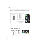
Table 2. Front Panel Header Pins HD_LED PWRLED RESET PWRSW No Connect Empty Pin Signal 1 HD_PWR 3 HDA# 2 HDR_BLNK_GRN 4 HDR_BLNK_YEL 5 GND 7 FP_RESET# 6 SWITCH_ON# 8 GND 9 No Connect 10 Empty In/Out Out Out Out Out In In Description Hard disk drive LED pulls up to +5V Hard disk drive active LED Front panel green light Front panel yellow light Ground Reset switch Power switch Ground USB Headers This motherboard contains six (6) USB 2.0 ports that are exposed on the rear panel of the chassis (Figure 2). The motherboard also contains one 10-pin internal header connectors onboard that can be used to connect an optional external bracket containing two (2) more USB 2.0 ports. 1. Secure the bracket to either the front or rear panel of your chassis (not all chassis are equipped with the front panel option). 2. Connect the end of the cable to the USB 2.0 header on the motherboard. Table 3. USB 2.0 Header Pins Connector Pin USB 2.0 Header Connector 1 3 5 7 9 Pin 2 4 6 8 10 Signal 5V_DUAL DD+ GND Empty Signal 5V_DUAL DD+ GND No Connect Card Edge EVGA 17
-
 1
1 -
2
-
3
-
4
-
5
-
6
-
7
-
8
-
9
-
10
-
11
-
12
-
13
-
14
-
15
-
16
-
17
-
18
-
19
-
 20
20 -
 21
21 -
 22
22 -
 23
23 -
 24
24 -
 25
25 -
 26
26 -
 27
27 -
 28
28 -
 29
29 -
 30
30 -
31
-
32
-
33
-
34
-
35
-
36
-
37
-
38
-
39
-
40
-
41
-
42
-
43
-
44
-
45
-
46
-
47
-
48
-
49
-
50
-
51
-
52
-
53
-
54
-
55
-
56
-
57
-
58
-
59
-
60
-
61
-
62
-
63
-
64
-
65
-
66
-
67
-
68
-
69
-
70
-
71
-
72
-
73
-
74
-
75
-
76
-
77
 |
 |
