EVGA 122-YW-E173-TR User Guide - Page 27
Fan Connections - nforce
 |
UPC - 843368006839
View all EVGA 122-YW-E173-TR manuals
Add to My Manuals
Save this manual to your list of manuals |
Page 27 highlights
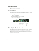
Fan Connections There are five fan connections on the motherboard. The fan speed can be detected and viewed in the PC Health Status section of the CMOS Setup. The fans are automatically turned off after the system enters S3, S4 and S5 mode. Note that the CPU fan cable can be either a 3-pin or a 4-pin connector. Connect a 3-pin connector to pins 1, 2, and 3 on the motherboard connector. CPU Fan Connector 4 3 2 GND SENSE PWR CONTROL 3 2 Auxiliary Fan Connector GND +12V SENSE EVGA nForce 750i SLI SPP/MCP Fan Connector 3 2 Install the fan over the nForce 750i SLI SPP to draw heat from the MCP. The fan plugs into a 3-pin connector. GND +12V SENSE EVGA 19
-
 1
1 -
2
-
3
-
4
-
5
-
6
-
7
-
8
-
9
-
10
-
11
-
12
-
13
-
14
-
15
-
16
-
17
-
18
-
19
-
20
-
21
-
 22
22 -
 23
23 -
 24
24 -
 25
25 -
 26
26 -
 27
27 -
 28
28 -
 29
29 -
 30
30 -
 31
31 -
 32
32 -
33
-
34
-
35
-
36
-
37
-
38
-
39
-
40
-
41
-
42
-
43
-
44
-
45
-
46
-
47
-
48
-
49
-
50
-
51
-
52
-
53
-
54
-
55
-
56
-
57
-
58
-
59
-
60
-
61
-
62
-
63
-
64
-
65
-
66
-
67
-
68
-
69
-
70
-
71
-
72
-
73
-
74
-
75
-
76
-
77
 |
 |

EVGA
19
Fan Connections
There are five fan connections on the motherboard. The fan speed can be detected and
viewed in the
PC Health Status
section of the CMOS Setup. The fans are automatically
turned off after the system enters S3, S4 and S5 mode.
Note that the CPU fan cable can
be either a 3-pin or a 4-pin
connector. Connect a 3-pin
connector to pins 1, 2, and 3 on
the motherboard connector.
3
2
GND
+12V
SENSE
CPU Fan
Connector
4
3
2
GND
SENSE
PWR
CONTROL
EVGA nForce 750i SLI SPP/MCP Fan Connector
Install the fan over the nForce 750i SLI SPP
to draw heat from the MCP. The fan plugs
into a 3-pin connector.
3
2
GND
+12V
SENSE
Auxiliary Fan
Connector