EVGA P67 FTW User Guide
EVGA P67 FTW Manual
 |
View all EVGA P67 FTW manuals
Add to My Manuals
Save this manual to your list of manuals |
EVGA P67 FTW manual content summary:
- EVGA P67 FTW | User Guide - Page 1
User Guide EVGA P67 FTW Motherboard - EVGA P67 FTW | User Guide - Page 2
EVGA P67 FTW Motherboard 2 - EVGA P67 FTW | User Guide - Page 3
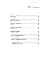
10 Unpacking ...10 Equipment ...10 EVGA P67 FTW Motherboard 12 Hardware Installation 15 Safety Instructions 15 Preparing the Motherboard 16 Installing the CPU 16 Installing the CPU Fan 17 Installing System Memory (DIMMs 18 Installing the Motherboard 19 Installing the I/O Shield 19 - EVGA P67 FTW | User Guide - Page 4
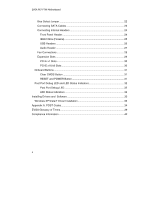
EVGA P67 FTW Motherboard Bios Select Jumper 22 Connecting SATA Cables 23 Connecting Internal Headers 24 Front Panel Header 24 IEEE1394a (Firewire 25 USB Indicators 32 Installing Drivers and Software 33 Windows XP/Vista/7 Driver Installation 33 Appendix A. POST Codes 34 EVGA Glossary of Terms - EVGA P67 FTW | User Guide - Page 5
EVGA P67 FTW Motherboard List of Figures Figure 1. Figure 2. Figure 3. EVGA P67 FTW Motherboard Layout 15 Chassis Back Panel Connectors 14 PW1 Motherboard Connector 21 5 - EVGA P67 FTW | User Guide - Page 6
EVGA P67 FTW Motherboard Before You Begin... Thank you for purchasing the EVGA P67 FTW Motherboard. This board is based off of the new Intel P67 chipset with native support for SATA III/6G for the performance you demand, delivered when you need it. As always this board comes with the added bonus - EVGA P67 FTW | User Guide - Page 7
necessary to install and connect your new EVGA P67 FTW Motherboard. However, it does not contain the following items that must be purchased separately to make the motherboard functional. Intel Socket 1155 Processor DDR3 System Memory Socket 775 or 1155/1156 CPU cooler for the processor PCI Express - EVGA P67 FTW | User Guide - Page 8
EVGA P67 FTW Motherboard EVGA P67 FTW Motherboard Motherboard Specifications Size EATX form factor of 12 inches x 10.3 inches Microprocessor support Intel Socket 1155 Processor Operating systems: Supports Windows XP/Vista/7 32 and 64 bit Contains Intel P67 chipset System Memory support Supports - EVGA P67 FTW | User Guide - Page 9
EVGA P67 FTW Motherboard Six (6) onboard SATA ports up to 3.0 Gb/s (300 M/s) data transfer rate Two (2) SATA ports up to 6.0 Gb/s (600 M/s) data transfer rate Six SATA ports from P67Chipset support for RAID 0, RAID 1, RAID 0+1, RAID5 and RAID 10 Two ESATA supports 3.0 Gb/s (on I/O panel) Onboard LAN - EVGA P67 FTW | User Guide - Page 10
following accessories are included with the EVGA P67 FTW Motherboard: The EVGA P67 FTW Motherboard This PCI-E motherboard contains the Intel P67 chipset and is SLI-ready for 2 or 3-way SLI configurations. 1 - Visual Guide Helps to quickly and visually guide you through the hardware installation of - EVGA P67 FTW | User Guide - Page 11
EVGA P67 FTW Motherboard 1 - I/O Shield Fan Exhausts Air from the IO Shield out of the rear of the case. Attaches to IO Shield. 2 - 2-Port SATA Power Cables Allows a Molex power connector to adapt to a SATA power connector. 1 - 2-Port USB 2.0 / 1394a Firewire Bracket Provides two additional USB - EVGA P67 FTW | User Guide - Page 12
drivers and software needed to setup the motherboard. 1 - User Manual Contains Information needed to properly install and configure your EVGA Motherboard. EVGA P67 FTW Motherboard The EVGA P67 FTW Motherboard with the Intel P67 chipset is an SLI-ready motherboard. Figure 1 shows the motherboard - EVGA P67 FTW | User Guide - Page 13
25 17 17 17 17 17 16 23 15 14 13 4 EVGA P67 FTW Motherboard 20 4 22 1 21 11 6 12 3 4 24 9 10 8 1. CPU Socket 1155 2. Intel P67 Chipset 3. DDR3 DIMM Slots 1 - 4 4. Fan Connectors 5. 24-Pin ATX Power Connector 6. Motherboard Battery 7. SATA III connectors 8. SATA II Connectors 9. Debug LED - EVGA P67 FTW | User Guide - Page 14
EVGA P67 FTW Motherboard 2 3 6 6 1 3 4 3 1. Clear CMOS Button 2. IEEE 1394a (Firewire) Port 3. USB 2.0 ports (six) 4. ESATA ports 5. USB 3.0 ports (two) 6. Dual LAN Ports with LEDs to indicate status: Activity LED Status Off Blinking (Green) Description No data transmission Data - EVGA P67 FTW | User Guide - Page 15
EVGA P67 FTW Motherboard Hardware Installation This section will guide you through the installation of the motherboard. The topics covered in this section are: Preparing the motherboard Installing the CPU Installing the CPU fan Installing the memory Installing the motherboard Connecting cables - EVGA P67 FTW | User Guide - Page 16
EVGA P67 FTW Motherboard Preparing the Motherboard Installing the CPU Be very careful when handling the CPU. Hold the processor only by the edges and do not touch the bottom of the processor. Use the following procedure to install the CPU onto the motherboard: Unhook the socket lever by pushing down - EVGA P67 FTW | User Guide - Page 17
EVGA P67 FTW Motherboard Align the notches in the processor with the notches on the socket. Lower the processor straight down into the socket with out tilting or sliding it into the socket. Note: Make sure the CPU is fully seated and level in the socket. Close the load plate over the CPU and - EVGA P67 FTW | User Guide - Page 18
EVGA P67 FTW Motherboard Installing System Memory (DIMMs) Your new motherboard has four 240-pin slots for DDR3 memory. These slots support 1GB, 2GB and 4GB DDR3 DIMMs. There must be at least one memory slot populated to ensure normal operation. Use the following the recommendations for installing - EVGA P67 FTW | User Guide - Page 19
EVGA P67 FTW Motherboard Installing the Motherboard The sequence of installing the motherboard into a system case depends on the chassis you are using and if you are replacing an existing motherboard or working with an empty system case. Determine if it would be easier to make all the connections - EVGA P67 FTW | User Guide - Page 20
EVGA P67 FTW Motherboard Securing the Motherboard into a System Case Most system cases have a base with mounting studs or spacers to allow the motherboard to be secured to the chassis and help to prevent short circuits. If there are studs that do not align with a mounting hole on the motherboard, it - EVGA P67 FTW | User Guide - Page 21
EVGA P67 FTW Motherboard Expansion slots CMOS Clear Button 24-pin ATX Power (PW1) PW1 is the main power supply connector located along the edge of the board next to the DIMM slots. Make sure that the power supply cable and pins are properly aligned with the connector on the motherboard. Firmly - EVGA P67 FTW | User Guide - Page 22
EVGA P67 FTW Motherboard 8-pin ATX 12V Power (PW12-1 & PW12-2) PW12-1 & PW12-2, the 8-pin ATX 12V power connection, is used to provide power to the CPU. Align the pins to the connector and press firmly until seated. +12V GND BIOS Select Switch The BIOS Select Switch is located directly to the right - EVGA P67 FTW | User Guide - Page 23
EVGA P67 FTW Motherboard Connecting SATA Cables The SATA II connector is used to connect the SATA II device to the motherboard. These connectors support the thin SATA II cables for primary storage devices. The current SATA II interface allows up to 300MB/s data transfer rate. There are six (6) - EVGA P67 FTW | User Guide - Page 24
EVGA P67 FTW Motherboard Connecting Internal Headers Front Panel Header The front panel header on this motherboard is one connector used to connect the LED is off. When the system is in S1, S3, S4 status, the LED will blink. Note: Some system cases do not have all four cables. Be sure to match - EVGA P67 FTW | User Guide - Page 25
EVGA P67 FTW Motherboard IEEE 1394a (Firewire) The IEEE 1394a cases are equipped with the front panel option). Connect the end of the cable(s) to the IEEE 1394a headers on the motherboard. Table 3. IEEE 1394a Connector Pins Connector IEEE 1394a Connector 10 9 8 7 6 5 4 3 2 1 Pin 1 - EVGA P67 FTW | User Guide - Page 26
EVGA P67 FTW Motherboard USB Headers This motherboard contains six (6) USB 2.0 ports that are exposed on the rear panel of the chassis (Figure 2). The motherboard also contains two 10-pin internal header connectors onboard that can be used to connect an optional external bracket containing up to - EVGA P67 FTW | User Guide - Page 27
EVGA P67 FTW Motherboard Audio The audio connector supports HD audio standard and provides two kinds of audio output choices: the Front Audio and the Rear Audio. The Front Audio supports re-tasking function. Table 5. Front Audio Connector Connector Front Audio Connector 10 9 8 7 6 5 4 3 - EVGA P67 FTW | User Guide - Page 28
EVGA P67 FTW Motherboard AUX Fan Ground +12V Sense Control Fan Connections There are seven fan connections on the motherboard. The fan speed can be detected and viewed in the BIOS. The fans are automatically turned off after the system enters S3, S4 and S5 mode. Ground +12V Sense Control System - EVGA P67 FTW | User Guide - Page 29
EVGA P67 FTW Motherboard Expansion Slots The EVGA P67 FTW Motherboard contains six (7) expansion slots, three (5) PCI-E x16 length slots and three (2) PCI-E x1 slots. For a full list of PCI-E graphic cards supported by this motherboard, visit: www.EVGA.com/Products 7 6 5 4 3 2 1 Slot - EVGA P67 FTW | User Guide - Page 30
EVGA P67 FTW Motherboard PCI-E x1 Slots There are two PCI-E x1 slots that are designed Cards and PCI-E x1, x4, x8 and x16 devices. The design of this motherboard supports multiple Graphics Card technologies such as SLI or CrossFireX. When installing a PCI-E Graphics Card, be sure the retention clip - EVGA P67 FTW | User Guide - Page 31
EVGA P67 FTW Motherboard Onboard Buttons These onboard buttons include RESET, POWER and Clear CMOS. These functions allow you to easily reset the system, turn on/off the system, or clear the CMOS. Clear CMOS Button The motherboard uses the CMOS RAM system during troubleshooting situations. The - EVGA P67 FTW | User Guide - Page 32
EVGA P67 FTW Motherboard Post Port Debug LED and LED Status Indicators Post Port Debug LED Provides two-digit POST codes to show why the system may be failing to boot. It is useful during troubleshooting situations. This Debug LED will also display current CPU socket temperatures after the system - EVGA P67 FTW | User Guide - Page 33
been shipped with the EVGA P67 FTW Motherboard contains the following software and drivers: Chipset Drivers Audio Drivers RAID Drivers LAN Drivers Matrix Storage VIA USB 3.0 Drivers EVGA E-LEET User's Manual Windows XP/Vista/Win 7 Driver Installation 1. Insert the EVGA P67 installation CD for the - EVGA P67 FTW | User Guide - Page 34
EVGA P67 FTW Motherboard Appendix A. POST Codes This section provides the AMI POST Codes (Table 6) for the EVGA P67 FTW Motherboard during system boot up. The POST Codes are displayed on the Debug LED readout located directly onboard the motherboard. This Debug LED will also display current CPU - EVGA P67 FTW | User Guide - Page 35
EVGA P67 FTW Motherboard 1C 1D- OEM pre-memory initialization codes 2A 2B Memory initialization. Serial Presence Detect (SPD) data reading 2C Memory initialization. Memory presence detection 2D Memory initialization. Programming memory timing information 2E Memory initialization. Configuring memory - EVGA P67 FTW | User Guide - Page 36
EVGA P67 FTW Motherboard is failed 5A Internal CPU error 5B reset PPI is not available 5C- Reserved for future AMI error codes 5F E0 S3 Resume is stared (S3 Resume PPI is called by the DXE IPL) E1 S3 Boot Installation of the South Bridge Runtime Services 63- CPU DXE initialization is started 67 68 - EVGA P67 FTW | User Guide - Page 37
EVGA P67 FTW Motherboard OEM DXE initialization codes 8F 90 Boot Device Selection (BDS) phase is started 91 Driver connecting is started 92 PCI Bus devices connect 99 Super IO Initialization 9A USB initialization is started 9B USB Reset 9C USB Detect 9D USB Enable 9E- Reserved for future AMI - EVGA P67 FTW | User Guide - Page 38
EVGA P67 FTW Motherboard AD Ready To Boot event AE Legacy Boot event AF Exit Boot Services event B0 Runtime Set Virtual Address MAP Begin B1 Runtime Set Virtual Address MAP End B2 Legacy Option ROM Initialization B3 System Reset B4 USB hot plug B5 PCI bus hot plug B6 Clean-up of NVRAM B7 - EVGA P67 FTW | User Guide - Page 39
EVGA P67 FTW Motherboard EVGA Glossary of Terms 1337 - This is reserved for EVGA level elite AC - Alternating Current ACPI of base system bus) BIOS - Basic Input Output System CD-ROM - Compact Disc Read-Only Memory CMOS - Complementary Metal-Oxide Semiconductor CPU - Central Processing Unit D-ICE - EVGA P67 FTW | User Guide - Page 40
EVGA P67 FTW Motherboard FSB - Front Side Bus FTW - For The Win! GHz - Gigahertz GPU - Graphics Processing Unit HDD - Institute of Electrical and Electronics Engineers IGP - Integrated Graphics Processors IMC - Integrated memory controller IRQ - Interrupt Request JBOD - Just a Bunch of Disks JEDEC - - EVGA P67 FTW | User Guide - Page 41
Quad Data Rate QPI - Quick Path Interconnect RAID - Redundant Array of Inexpensive Disks RGB - Computer System Interface SFR - Split Frame Rendering SLI - Scalable Link Interface SPD - Serial USB - Universal Serial Bus VDroop - V-core Voltage Drop VGA - Video Graphics Array EVGA P67 FTW Motherboard - EVGA P67 FTW | User Guide - Page 42
EVGA P67 FTW Motherboard instructions, may cause harmful interference to radio communications. However, there is no guarantee that interference will countries. Other company, products and service names may be trademarks or service marks of others. EVGA reserves the right to terminate this license
-
 1
1 -
 2
2 -
 3
3 -
 4
4 -
 5
5 -
 6
6 -
 7
7 -
8
-
9
-
10
-
11
-
12
-
13
-
14
-
15
-
16
-
17
-
18
-
19
-
20
-
21
-
22
-
23
-
24
-
25
-
26
-
27
-
28
-
29
-
30
-
31
-
32
-
33
-
34
-
35
-
36
-
37
-
38
-
39
-
40
-
41
-
42
 |
 |

User Guide
EVGA P67 FTW
Motherboard