Electrolux E36GC76GPS Installation Instructions - Page 1
Electrolux E36GC76GPS - 36" Pro-Style Gas Rangetop Manual
 |
UPC - 057112097985
View all Electrolux E36GC76GPS manuals
Add to My Manuals
Save this manual to your list of manuals |
Page 1 highlights
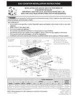
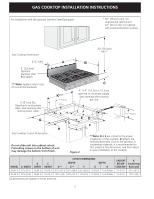
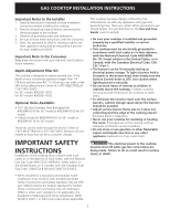
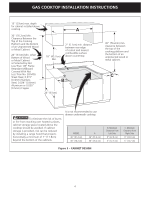
GAS COOKTOP INSTALLATION INSTRUCTIONS INSTALLATION AND SERVICE MUST BE PERFORMED BY A QUALIFIED INSTALLER. IMPORTANT: SAVE FOR LOCAL ELECTRICAL INSPECTOR'S USE. READ AND SAVE THESE INSTRUCTIONS FOR FUTURE REFERENCE. If the information in this manual is not followed exactly, a fire or explosion may result causing property damage, personal injury or death. FOR YOUR SAFETY: - Do not store or use gasoline or other flammable vapors and liquids in the vicinity of this or any other appliance. - WHAT TO DO IF YOU SMELL GAS: • Do not try to light any appliance. • Do not touch any electrical switch; do not use any phone in your building. • Immediately call your gas supplier from a neighbor's phone. Follow the gas supplier's instructions. • If you cannot reach your gas supplier, call the fire department. - Installation and service must be performed by a qualified installer, service agency or the gas supplier. For Standard Installation: Gas Cooktop Dimensions A * 30" (76.2cm) min. for unprotected cabinet and 24" (61cm) min. for cabinet 30"(76.2cm) with protected bottom surface. Min.* B Gas Cooktop Cutout Dimensions 2"(5.1cm) Dia. Opening to route power cable. Seal opening after routing power cable. 3"(7.6cm) 21/2" (6.4cm) G H C 4" X 4" (10.2cm x 10.2cm) opening to route gas supply. Seal opening after routing gas line J 71/4" (18.4cm) 2"(5.1cm) 1" (2.5cm) E D F Figure 1 **Note: D & E are critical to the proper installation of the cooktop. D reflects the finished dimension. Due to the variation in countertop materials, it is recommended to first undercut this dimension, and then adjust it upon installation of the cooktop. CUTOUT DIMENSIONS B. C. WIDTH MODEL A. WIDTH DEPTH HEIGHT D** E** F DEPTH G H J. HEIGHT BELOW COOKTOP 36 (91.4) 357/8 (91.1) 25 (63.5) 7¾ (19.7) 3515/16 (91.3) 353/16 (89.4) 351/8 (89.2) 22 (55.9) 11/8 (2.9) Max. 7½ (19.1) 30 (76.2) 297/8 (75.9) 25 (63.5) 7¾ (19.7) 2915/16 (76) 293/16 (74.1) 291/8 (74) 22 (55.9) 11/8 (2.9) Max. 7½ (19.1) All dimensions are stated in inches and (cm). NOTE: Wiring diagrams for this cooktop are enclosed in this booklet Printed in Canada 1 318201493 (1101) Rev. B English - pages 1-8 Español - páginas 9-16 Français - pages 17-23 Wiring Diagram page - 24
-
 1
1 -
 2
2 -
 3
3 -
 4
4 -
 5
5 -
 6
6 -
 7
7 -
8
-
9
-
10
-
11
-
12
-
13
-
14
-
15
-
16
-
17
-
18
-
19
-
20
-
21
-
22
-
23
-
24
 |
 |