Electrolux EI24ID81SS Wiring Diagram English - Page 1
Electrolux EI24ID81SS Manual
 |
View all Electrolux EI24ID81SS manuals
Add to My Manuals
Save this manual to your list of manuals |
Page 1 highlights
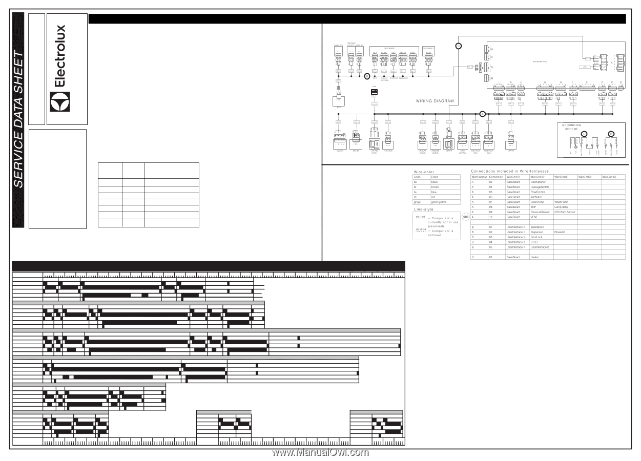
Service Mode EI 24ID81 P/N: SH808936683 EET After Cancel, press pad Heavy and Fast simultaneously for at least 4 seconds to access Service Mode. LED Auto, Led Heavy and Led Normal blink to indicate that Service mode is accesed. After accessed Service mode ( Led Auto, Led Heavy and Led Normal blinking): 1. Press pad Auto to show the first alarm code. - Led Auto blinks to indicate the machine is in Alarm Reading. - The first alarm code saved is shown in the display. For descriptions of alarm codes, please see Alarm Codes section. 2. Press pad Auto again to show the second alarm code. 3. Press pad Auto once more to show the third alarm code. 4. Press pad Auto the fourth time to move to Actuator Test. Press pad repeatedly will sequentially turn on one actuator at a time. - Led Auto is turned off. led Heavy blincks to indicate the machine is in Actuator Test. - The actuator number is shown in the display, see the following table for details. LED Test/Delete Alarm Memory After accessed Service mode ( Led Auto, Led Heavy and Led Normal blinking): 1. Press pad Heavy to start this function. - All LEDS and display blinks 5 seconds on 1 second off. - Buzzer beeps 5 seconds and then off. - The alarm codes saved in memory are erased. 2. The mode can be exit by pressing the CANCEL button, or waiting 60 seconds after last button pressing. Functional Test cycle After accessed Service mode (Led Auto, Led Heavy and Led Normal blinking): 1. Press pad Normal to start the test cycle.The cycle will not start if door is opened. - LED Normal blinks all the way through the whole cycle, even if after the cycle is finished The test cycle runs as a normal wash cycle. It can be cancelled or run to its end. damage of any kind arising from the use of this Service Data Sheet. nor assume any liability, for injury or North America cannot be responsible, repair trade. Electrolux Home Products considered acceptable in the appliance knowledge of these subjects generally mechanical training and a level of This informationSis inten ERdedVforI useC byE DATA persons having electrical and Number of Actuator pad Heavy Number pressed in display Actuator 4 4 Regeneration Valve 5 5 Drain Pump 6 6 Inlet Valve 7 7 Heater 8 8 Wash pump 9 9 Dispenser 10 10 Dry Fan 5. Press pad Auto when actuator number 10 is activated, the machine will cycle back to Alarm reading and show the first alarm code saved. 6. The mode can be exit by pressing the CANCEL button, or waiting 60 seconds after last button pressing. Cycle Selection Options Minutes Stemware 5 10 15 20 25 30 35 40 45 50 55 60 65 70 75 80 85 90 Cycle Selection Options 95 100 105 110 115 120 125 130 135 140 145 150 155 160 165 PreWash1 PreWash2 MainW ash ColdRinse HotRinse Dry Inlet Valve Circulation Pump Drain Pump Heater Dispenser Eco Inlet Valve Circulation Pump Drain Pump Heater Dispenser PW 1 PW 2 PreW ash3 PW 4 MainW ash ColdRinse1 ColdRinse2 HotRinse Dry Heavy PW1 PW2 PreWash3 MainW ash ColdRinse1 ColdRinse2 HotRinse Dry Inlet Valve Circulation Pump Drain Pump Heater Dispenser Normal/Auto PW Inlet Valve Circulation Pump Drain Pump Heater Dispenser MainW ash HotRinse Dry Normal Cycle (with light soil) Upper Inlet Valve Circulation Pump Drain Pump Heater Dispenser PW 1 PW 2 MainW ash CR HotRinse Dry Cycles may differ in behaviour from presentation above due to the dependence of turbidity, temperature and user input. E.g. Less/more phases; shorter/longer duration. Fast PW MainWash 1 MainWash2 HotRinse Rinse PreWash1 PreWash2 Inlet Valve Inlet Valve Circulation Pump Circ. Pump Drain Pump Drain Pump Heater Heater Dispenser Dispenser Minutes 5 10 15 20 25 30 35 40 45 50 55 60 65 70 Minutes 5 10 15 Line Test Inlet Valve Circ. Pump Drain Pump Heater Dispenser Minutes PreW ash 5 10 15 Wiring Diagram
-
 1
1 -
 2
2
 |
 |