Electrolux EI24ID81SS Wiring Diagram English - Page 2

Trouble Shooting Tips, Exploded View of Wash System - installation

Page 2 highlights

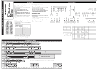
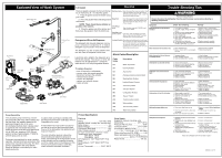
Exploded View of Wash System Tub Gasket Operation Trouble Shooting Tips Upper Spray arm Manifold Delivery Tube Small Tank Flex Wash Manifold Middle Spray Arm Lower Spray Arm Hose Tank Sump Valve Tank Hose Pressure Sensor Lower Spray Arm Support Circulation Motor and Heater Assembly Inlet Valve Turbidity Sump Fine Filter Drain Hose Coarse Filter Drain Pump The door gasket is pressed into the tub channel for an interference fit. To install the gasket: 1. Press the gasket across the header using your hands. 2. Press the gasket while stretching around the corners . NOTE: There should be no wrinkles or puckers in the corners. 3. Place the gasket end at the bottom and then press the gasket in from the bottom up. Detergent and Rinse Aid Dispenser The detergent and rinse aid dispenser is a one piece component consisting of a molded detergent cup and a built-in rinse aid dispenser. The detergent cup has a spring loaded cover and the rinse aid dispenser has a cover. Liquid rinse aid is added to the dispenser up to the fill line indicator. The amount of rinse aid released can be adjusted from 1, being the least amount, to 4, being the greatest amount. To replace dispenser: Starting a Cycle Open door,select the cycle and options: then press the "START" pad. The LED over the selected cycle pad will then flash. Close the door and the cycle will begin. Personal Injury Hazard Delay Start Open door,select the cycle and options; then press the "DELAY" pad. Each press of the pad will increase the delay time by 1 hour Always disconnect the dishwasher from the electrical power source before adjusting or replacing components. (1 to 24 hours). Cancelling a Symptom Check the Following Remedy cycle Open the door, press the "CANCEL" pad until a tone is heard. Dishwasher will not operate when turned on. 1. Fuse (blown or tripped). 2. 120 VAC supply wiring connection faulty. 1. Replace fuse or reset breaker. 2. Repair or replace wire fasteners at dishwasher junction box. Selecting a new cycle or option Open door, select the desired cycle and options; then press the "START" pad and close the door. The cycle will begin. 3. Electronic control board defective. 4. No 12 VAC power to control. 5. Motor (inoperative). 6. Door switch (open contacts). 7. Door latch not making contact with 3. Replace control board. 4. Replace control board. 5. Replace motor/impeller assembly. 6. Replace latch assembly. 7. Replace latch assembly. Locking Controls Open door and hold down the "air dry" pad for 5 seconds. The status window will display "loc" and the pads will be unresponsive. To unlock the control hold the "AIR DRY" door switch. 8. Touch pad circuit defective. 9. No indicator lamps illuminate when START or OPTIONS are pressed. 8. Replace console assembly. 9. Replace console assembly. pad down for 5 seconds until "loc goes out. Normal function will resume. Motor hums but will not start or run. 1. Motor (bad bearings). 2. Motor stuck due to prolonged non-use. 1. Replace motor assembly. 2. Rotate motor impeller. Alarm Codes/Description Code family i10 i20 Description Water Tap Closed Draining Problem Motor trips out on internal thermal overload protector. 1. Improper voltage. 2. Motor windings shorted. 3. Glass or foreign items in pump. 1. Check voltage. 2. Replace motor/impeller assembly. 3. Clean and clear blockage. Dishwasher runs but will not heat. 1. Heater element (open). 2. Electronic control board defective. 3. Wiring or terminal defective. 4. Hi-Limit thermostat defective. 1. Replace heater element. 2. Replace control board. 3. Repair or replace. 4. Replace thermostat. • shut off electricity to dishwasher, • remove outer door panel assembly, • disconnect wiring to the actuator, • remove the six screws, • remove the dispenser, • replace and reinstall screws, • rewire actuator. i30 Aqua Control Detergent cover will not latch or 1. Latch mechanism defective. 1. Replace dispenser. open. 2. Electronic control board defective. 2. Replace control board. i40 Analogue pressure sensor problem 3. Wiring or terminal defective. 4. Broken spring(s). 3. Repair or replace. 4. Replace dispenser. 5. Defective actuator. 5. Replace dispenser. i50 Washing Motor Problem i60 Heating Element Problem i70 Thermistor problem i80 Auto Door Opener Dishwasher will not pump out. 1. Drain restricted. 2. Electronic control board defective. 3. Defective drain pump. 4. Blocked impeller. 5. Open windings. 6. Wiring or terminal defective. 7. Defective Drain Valve. 1. Clear restrictions. 2. Replace control board. 3. Replace pump. 4. Check for blockage, clear. 5. Replace pump assembly. 6. Repair or replace. 7. Repair or replace. i90 Configuration Problem iB0 Sensor Problem iC0 Communication problem iD0 Tacho problem Dishwasher will not fill with water. 1. Water supply turned off. 2. Defective water inlet fill valve. 3. Check fill valve screen for obstructions. 4. Defective float switch. 5. Electronic control board defective. 6. Wiring or terminal defective. 7. Float stuck in "UP" position. 1. Turn water supply on. 2. Replace water inlet fill valve. 3. Disassemble and clean screen. 4. Repair or replace. 5. Replace control board. 6. Repair or replace. 7. Clean or replace float. iE0 Flow controller problem iF0 Water level problem Dishwasher water siphons out. Pump Assembly The circulation pump is driven by a brushless-sensorless AC-motor. When looking into the inlet hose, the impeller rotates by the permanent magnet rotor in the counter-clockwise direction when 3-phase power is applied by the main board electronics. When the motor drives the pump approximately at 2900 rpm, supplying 100% filtered water at a rate of approximately 17 GPM to all three spray arms at once. Draining is accomplished by using a smaller, separate, 3-phase brushless-sensorless drain pump motor mounted to the sump. The drain pump is connected to the sump directly. Speed is 2800rpm, controlled by the main board electronics. A rubber check valve flap is inserted at the discharge end of the drain outlet pipe, which is integrated on the sump. A raised drain hose loop section is routed on the side of the unit to help prevent/limit back flow out of the dishwasher. No additional such loops are required. The main circulation pump is removed by disconnecting both attached clamps and hoses, disconnecting the wiring harness to the pump assembly and un-strapping the pump out of the rubber mount in the basement. Wire harness connections include 2 earth tabs, motor connector and heater connector. Product Specifications Electrical Rating 120 Volts, 60Hz Separate Circuit..15 amp min.- 20 amp max. Motor (Amps 0.4 Heater Wattage 850 Total Amps (load rated 13.0 Water Temps controlled 5°F To assure success have outer door in place TempAssure (cycle dependent) Main Wash: 140°F Final Wash: 140°F Hi-TempAssure: 140°F Wash/149°F Final Rinse SanitizeAssure: 140°F Wash/156°F Final Rinse Hi-Limit Thermostat 200°F (93°C) Water Supply Suggested minimum incoming water temperature 120°F (49°C) Pressure (PSI) min./max 20/90 Connection (GHT 3/4" 11.5NH Consumption (Normal Cycle 3.1 - 7.4 U.S. gal., 11.5 - 28.1 liters Water valve flow rate (U.S. GPM 0.66 Water recirculation rate (U.S. GPM approx. 17 (@2900rpm) Water fill time 104 sec. Detergent left in dispenser. 1. Drain hose (high) loop too low. 2. Drain line connected to a floor drain not vented. 3. Drain valve or pump stuck open. 1. Repair to proper 32-inch minimum height. 2. Install air gap at counter top. 3. Repair or replace. 1. Detergent allowed to stand too long in dispenser. 2. Dispenser wet when detergent was added. 3. Detergent cover held closed or blocked by large dishes. 4. Improper incoming water temperature to properly dissolve detergent. 5. Spray arm blocked. 6. Is water getting into unit. 1. Instruct customer/user. 2. Instruct customer/user. 3. Instruct customer/user on proper loading of dishes. 4. Incoming water temperature of 120°F is required to properly dissolve dishwashing detergents. 5. Instruct customer/user. 6. Check fill valve repair or replace. Note: See "Detergent cover will not latch or open." 808936683 -A 26/2016

  • 1
  • 2

Trouble Shooting Tips
Exploded View of Wash System
Check the Following
1.
Fuse (blown or tripped).
2. 120 VAC supply wiring connection
faulty.
3. Electronic control board defective.
4.
No 12 VAC power to control.
5.
Motor (inoperative).
6.
Door switch (open contacts).
7. Door latch not making contact with
door switch.
8. Touch pad circuit defective.
9. No indicator lamps illuminate when
START or OPTIONS are pressed.
1.
Motor (bad bearings).
2. Motor stuck due to prolonged
non-use.
1.
Improper voltage.
2.
Motor windings shorted.
3.
Glass or foreign items in pump.
1.
Heater element (open).
2. Electronic control board defective.
3.
Wiring or terminal defective.
4.
Hi-Limit thermostat defective.
1.
Latch mechanism defective.
2. Electronic control board defective.
3.
Wiring or terminal defective.
4.
Broken spring(s).
5. Defective actuator.
1. Water supply turned off.
2. Defective water inlet fill valve.
3. Check fill valve screen for
obstructions.
4. Defective float switch.
5. Electronic control board defective.
6.
Wiring or terminal defective.
7.
Float stuck in “UP” position.
1.
Drain hose (high) loop too low.
2.
Drain line connected to a floor drain
not vented.
1.
Detergent allowed to stand too long in
dispenser.
2. Dispenser wet when detergent was
added.
3.
Detergent cover held closed or blocked
by large dishes.
4.
Improper incoming water
temperature to properly dissolve
detergent.
Always disconnect the dishwasher from the electrical power source before adjusting or
replacing components.
Personal Injury Hazard
Remedy
1.
Replace fuse or reset breaker.
2. Repair or replace wire fasteners at
dishwasher junction box.
3.
Replace control board.
4.
Replace control board.
5.
Replace motor/impeller assembly.
6.
Replace latch assembly.
7.
Replace latch assembly.
8.
Replace console assembly.
9.
Replace console assembly.
1.
Replace motor assembly.
2.
Rotate motor impeller.
1. Check voltage.
2.
Replace motor/impeller assembly.
3.
Clean and clear blockage.
1.
Replace heater element.
2.
Replace control board.
3.
Repair or replace.
4.
Replace thermostat.
1.
Replace dispenser.
2.
Replace control board.
3.
Repair or replace.
4.
Replace dispenser.
5.
Replace dispenser.
1.
Turn water supply on.
2.
Replace water inlet fill valve.
3.
Disassemble and clean screen.
4.
Repair or replace.
5.
Replace control board.
6.
Repair or replace.
7. Clean or replace float.
1. Repair to proper
32-inch minimum
height
.
2. Install air gap at counter top.
1. Instruct customer/user.
2. Instruct customer/user.
3. Instruct customer/user on proper
loading of dishes.
4.
Incoming water temperature of
120°F is required to properly
dissolve dishwashing detergents.
Symptom
Dishwasher will not operate when
turned on.
Motor hums but will not start or run.
Motor trips out on internal thermal
overload protector.
Dishwasher runs but will not heat.
Detergent cover will not latch or
open.
Dishwasher will not pump out.
Dishwasher will not fill with water.
Dishwasher water siphons out.
Detergent left in dispenser.
Tub Gasket
The door gasket is pressed into the tub channel
for an interference fit.
To install the gasket:
1.
Press the gasket across the header using
your hands.
2.
Press the gasket while stretching around
the corners .
NOTE:
There should be no wrinkles or
puckers in the corners.
3.
Place the gasket end at the bottom and
then press the gasket in from the bottom up.
3.
Repair or replace.
3. Drain valve or pump stuck open.
5.
Spray arm blocked.
6. Is water getting into unit.
5. Instruct customer/user.
6.
Check fill valve repair or replace.
7. Defective Drain Valve.
7.
Repair or replace.
1. Drain restricted.
2. Electronic control board defective.
3. Defective drain pump.
4.
Blocked impeller.
5.
Open windings.
6. Wiring or terminal defective.
1. Clear restrictions.
2.
Replace control board.
3.
Replace pump.
4. Check for blockage, clear.
5. Replace pump assembly.
6.
Repair or replace.
Note:
See "Detergent cover will not latch or open."
Alarm Codes/Description
Code
Description
family
i10
Water Tap Closed
i20
Draining Problem
i30
Aqua Control
i40
Analogue pressure sensor problem
i50
Washing Motor Problem
i60
Heating Element Problem
i70
Thermistor problem
i80
Auto Door Opener
i90
Configuration Problem
iB0
Sensor Problem
iC0
Communication problem
iD0
Tacho problem
iE0
Flow controller problem
iF0
Water level problem
Product Specifications
Electrical
Rating
...................................
120 Volts, 60Hz
Separate Circuit..15 amp min.- 20 amp max.
Motor (Amps)
............................................
0.4
Heater Wattage
.....................................
850
Total Amps (load rated)
.........................
13.0
Water Temps controlled
.........................
±5°F
To assure success have outer door in place
TempAssure (cycle dependent)
Main Wash:
140°F
Final Wash:
140°F
Hi-TempAssure: 140°F Wash/149°F Final
Rinse
SanitizeAssure: 140°F Wash/156°F Final
Rinse
Hi-Limit Thermostat
.................
200°F (93°C)
Water Supply
Suggested minimum incoming water
temperature
.............................
120°F (49°C)
Pressure (PSI) min./max
. .....................
20/90
Connection (GHT)
........................
3/4" 11.5NH
Consumption (Normal Cycle)
.......................
.............
3.1 - 7.4 U.S. gal., 11.5 - 28.1 liters
Water valve flow rate (U.S. GPM)
...........
0.66
Water recirculation rate (U.S. GPM)
..............
...............................
approx. 17 (@2900rpm)
Water fill time
...................................
104 sec.
Operation
Starting a Cycle
Open door,select the cycle and options: then
press the “START” pad. The LED over the
selected cycle pad will then flash. Close the
door and the cycle will begin.
Delay Start
Open door,select the cycle and options; then
press the “DELAY” pad. Each press of the
pad will increase the delay time by 1 hour
(1 to 24 hours).
Cancelling a
cycle
Open the door, press the “CANCEL” pad
until a tone is heard.
Selecting a new
cycle or option
Open door, select the desired cycle and
options; then press the “START” pad and
close the door. The cycle will begin.
Locking Controls
Open door and hold down the “air dry” pad
for 5 seconds. The status window will display
“loc” and the pads will be unresponsive.
To unlock the control hold the “AIR DRY”
pad down for 5 seconds until “loc goes out.
Normal function will resume.
The circulation pump is driven by a brush-
less-sensorless AC-motor. When looking into
the inlet hose, the impeller rotates by the
permanent magnet rotor in the coun-
ter-clockwise direction when 3-phase power
is applied by the main board electronics.
When the motor drives the pump approxima-
tely at 2900 rpm, supplying 100% filtered
water at a rate of approximately 17 GPM to
all three spray arms at once.
Draining is accomplished by using a smaller,
separate, 3-phase brushless-sensorless drain
pump motor mounted to the sump. The drain
pump is connected to the sump directly.
Speed is 2800rpm, controlled by the main
board electronics.
A rubber check valve flap is inserted at the
discharge end of the drain outlet pipe, which is
integrated on the sump.
A raised drain hose loop section is routed on
the side of the unit to help prevent/limit back
flow out of the dishwasher. No additional such
loops are required.
The main circulation pump is removed by
disconnecting both attached clamps and
hoses, disconnecting the wiring harness to the
pump assembly and un-strapping the pump
out of the rubber mount in the basement. Wire
harness connections include 2 earth tabs,
motor connector and heater connector.
Pump Assembly
To replace dispenser:
°
shut off electricity to dishwasher,
°
remove outer door panel assembly,
°
disconnect wiring to the actuator,
°
remove the six screws,
°
remove the dispenser,
°
replace and reinstall screws,
°
rewire actuator.
Detergent and Rinse Aid Dispenser
The detergent and rinse aid dispenser is a one
piece component consisting of a molded
detergent cup and a built-in rinse aid dispenser.
The detergent cup has a spring loaded cover
and the rinse aid dispenser has a cover.
Liquid rinse aid is added to the dispenser up to
the fill line indicator. The amount of rinse aid
released can be adjusted from 1, being the
least amount, to 4, being the greatest amount.
Upper Spray arm
Manifold
Sump
Inlet Valve
Coarse Filter
Turbidity
Fine
Filter
Middle Spray Arm
Pressure
Sensor
Delivery Tube
Drain Pump
Drain Hose
Circulation Motor
and Heater Assembly
Lower Spray Arm
Flex Wash
Manifold
Lower Spray Arm
Support
Small Tank
Valve Tank
Hose
Hose Tank
Sump
808936683 -A 26/2016