Electrolux EI30DD10KS Complete Owner's Guide (English) - Page 13
Important
 |
View all Electrolux EI30DD10KS manuals
Add to My Manuals
Save this manual to your list of manuals |
Page 13 highlights
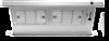
Installation 13 Install Ductwork Re-attach Transition Duct The Transition Base must be installed with the flange at the top. Position the duct Transition Cover on the Transition Base for the discharge direction selected. The top edge of the duct Transition Cover must be under the tabs of the Transition Base. Down Discharge - Attach the transition with 4 screws as shown. Discharge Duct Transition Cover Transition Base (4) Phillips Head Screws Discharge Down (as supplied) Left or Right Discharge - Remove the Phillips head screw from the chassis. Attach the transition with 5 screws as shown. (4) Phillips Head Screws Discharge Right Remove Phillips Head Screw from Right Hole and Attach as Shown Connect the ductwork - Use galvanized or aluminum duct in 8" or 10" round or 3 ¼" x 14" size, or a combination of both. PVC duct should be used if installing under a poured concrete slab. Use the shortest and straightest duct run possible. NOTE Local building codes must be followed in specifying approved type and specifications of ALL duct used. Always use an appropriate roof or wall cap with damper. IMPORTANT All ductworks must be as installed as per local codes. Duct Tape Over Seam and Screw Air Flow Discharge Remove Phillips Head Screw from Left Hole and Reattach as Shown Discharge Left (4) Phillips Head Screws Screw Connect Downdraft to Power - Plug the downdraft's power cord into the outlet. - Make sure the power cord is routed beneath the appliance and away from heat generated by the cooktop. Install Cooktop - Align the cooktop with the downdraft and fasten cooktop in place. NOTE Accurate alignment of cooktop and downdraft is necessary to ensure that there is no interference when air vent is raised and lowered. There should be a gap of 1/8" between the back of the cooktop and the front of the downdraft cover.
-
 1
1 -
2
-
3
-
4
-
5
-
6
-
7
-
 8
8 -
 9
9 -
 10
10 -
 11
11 -
 12
12 -
 13
13 -
 14
14 -
 15
15 -
 16
16 -
 17
17 -
 18
18
 |
 |
