Electrolux EI30GS55LB Installation Instructions (All Languages) - Page 10
Models with Sealed Top Burners
 |
View all Electrolux EI30GS55LB manuals
Add to My Manuals
Save this manual to your list of manuals |
Page 10 highlights
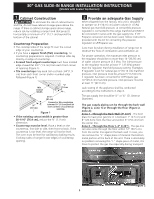
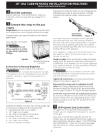
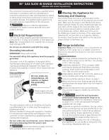
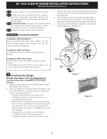
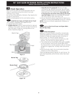
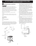
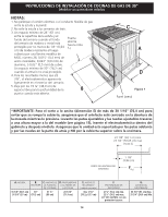
30" GAS SLIDE-IN RANGE INSTALLATION INSTRUCTIONS (Models with Sealed Top Burners) 10.4 Adjust the "low" setting for regular surface burner valves (Figure 11) Be careful when performing this operation. a. Push in and turn control to LITE until burner ignites. b. Quickly turn knob to LOWEST POSITION. c. If burner goes out, reset control to OFF. d. Remove the surface burner control knob. e. Insert a thin-bladed screwdriver into the hollow valve stem and engage the slotted screw inside. Flame size can be increased or decreased with the turn of the screw. Turn counterclockwise to increase flame size. Turn clockwise to decrease flame size. Adjust flame until you can quickly turn knob from LITE to LOWEST POSITION without extinguishing the flame. Flame should be as small as possible without going out. Note: Air mixture adjustment is not required on surface burners. Counterclockwise Increase Flame Clockwise Decrease Flame B A Dual Valve Hollow Valve Stem Figure 11 Regular Valve 10.5 Adjust the "LOW" Setting of the Dual Burner Surface Valve (Figure 11) Note: On the dual valve the low setting of each portion should be adjusted individually. a. Push in and turn control to LITE until the rear portion of the bridge burner ignites only. b. Quickly turn knob to LOWEST POSITION. c. If burner goes out, reset control to OFF. d. Remove the surface burner control knob. e. The rear or outer portion of the burner flame size can be increased or decreased with the turn of the screw A. Use screw B to adjust the flame size of the center portion of the burner. Turn counterclockwise the screw to increase flame size. Turn clockwise the screw to decrease flame size. Adjust flame until you can quickly turn knob from LITE to LOWEST POSITION without extinguishing the flame. Flame should be as small as possible without going out. Note: Air mixture adjustment is not required on surface burners. 10.6 Operation of Oven Burners and Oven Adjustments 10.6.1 Electric Ignition Burners Operation of electric igniters should be checked after range and supply line connectors have been carefully checked for leaks, and range has been connected to electric power. The oven burner is equipped with an electric control system as well as an electric oven burner igniter. If your model is equipped with a waist-high broil burner igniter, it will also have an electric burner igniter. These control systems require no adjustment. When the oven is set to operate, current will flow to the igniter. It will "glow" similar to a light bulb. When the igniter has reached a temperature sufficient to ignite gas, the electrically controlled oven valve will open and flame will appear at the oven burner. There is a time lapse from 30 to 60 seconds after thermostat is turned ON before the flame appears at the oven burner. When the oven reaches the display setting, the glowing igniter will go off. The burner flame will go "out" in 20 to 30 seconds after igniter goes "OFF". To maintain any given oven temperature, this cycle will continue as long as the display is set to operate. After removing all packing materials and literature from the oven: a) Set the oven to BAKE at 300°F. See Use & Care Guide for operating instructions. b) Within 60 seconds the oven burner should ignite. Check for proper flame, and allow the burner to cycle once. Reset controls to off. c) If your model is equipped with a high-waist broiler, set oven to broil. See Use & Care Guide for operating instructions. d) Within 60 seconds the broil burner should ignite. Check for proper flame. Reset controls to off. Lower Oven Baffle (removable) Waist-High Air Burner Shutter Lower Oven Bottom Air Shutter (removable) Figure 12 10
-
 1
1 -
2
-
3
-
4
-
 5
5 -
 6
6 -
 7
7 -
 8
8 -
 9
9 -
 10
10 -
 11
11 -
 12
12 -
 13
13 -
 14
14 -
 15
15 -
16
-
17
-
18
-
19
-
20
-
21
-
22
-
23
-
24
-
25
-
26
-
27
-
28
-
29
-
30
-
31
-
32
-
33
-
34
-
35
-
36
-
37
-
38
-
39
-
40
 |
 |
