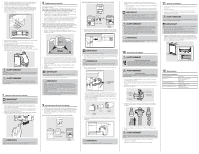
Electrolux EIDW1815US Installation Instructions English - Page 2
Important, Warning
 |
View all Electrolux EIDW1815US manuals
Add to My Manuals
Save this manual to your list of manuals |
Page 2 highlights
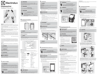
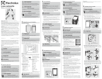
5. Adjust the four leveling legs at the bottom of the dishwasher after measuring the height of the cabinet opening from under the countertop to the floor. (See Step 8, Leveling the Dishwasher.) 6. Locate the hot water supply line and the power cable. 7. Place the dishwasher so the power cable is in the center channel of the dishwasher base. To prevent the electrical cable from being pinched when you push the dishwasher into place, use duct tape or cable ties to secure the electrical cable to the channel. Drain Hose 2 Hot Water Supply Line 8. Pull the drain hose through the hole in the sink cabinet side wall. Keep it free of kinks. 9. Make sure the hot water supply line is not twisted, and then connect the hot water supply line to the elbow joint. 10. Slide the dishwasher carefully into the installation space. If possible, gently pull any excess lengths of water supply line, drain hose, or power cable back as you move the dishwasher. Get a second or third person to help you do this if necessary. WARNING DO NOT place the dishwasher on the water supply line, drain hose, or power cable. Make sure none of the lines get folded or twisted during installation. WARNING DO NOT place hands under the dishwasher when moving. Always hold under the tub NOT the bottom of the unit. Keep clear of sharp edges. 7 Leveling the Dishwasher IMPORTANT Dishwasher must be level for proper dish rack operation and wash performance. 1. Open the door and hold level against the top of the tub to check if it is level side to side. Adjust the front legs until level. 2. Remove the lower basket and place the level in the basket channel to check if it is level front to back. Adjust the rear legs until level. 3. Open the door and check if the door hits the tub of the dishwasher. Adjust front leveling legs to align the door to the tub. NOTE Turn leveling leg clockwise (left) to lower the leg and counter clockwise (right) to raise the leg. 8 Securing the Dishwasher You must fix the dishwasher to the countertop or cabinet side walls for additional stability and safety. If securing to the countertop (wood or other material that will not be damaged by drilling), follow the instructions below. 1. Put a large towel into the bottom of the dishwasher to prevent wood shavings or a dropped screw from falling into the dishwasher. 2. Verify that the installation brackets are firmly attached to the top of the unit using screws ST3.5*9 provided with the unit. 3. Carefully drill screw holes into the underside of the counter top by passing the drill bit up through the screw holes in each installation bracket, making sure the diameter of the hole is smaller than the diameter of the screw. 4. Insert screws ST4*14 up through the brackets, and then tighten to secure the dishwasher to the countertop. If securing to the side cabinets (the countertop is made of granite, marble, or any other material that can be damaged by drilling), follow the instructions below. 1. Put a large towel into the bottom of the dishwasher to prevent wood shavings or a dropped screw from falling into the dishwasher. 2. Remove the adjustment caps with the tip of a screwdriver. The caps are just inside the tub near the middle of the tub on both sides. Connecting to drain with a garbage disposal unit with and without an air gap. Air gap Hose clamp No air gap Drain hose 2 Hose clamp 3. The drain hose molded end will fit 5/8", 3/4", or 1" diameter connections on the air gap, waster tee, or disposer. Cut on the marked line as required for your installation. Spacer caps Cutting Lines 1" 3/4" 5/8" Adjustment caps 3. Drill a hole into the sides of the kitchen cabinet on both sides by carefully passing a drill bit through the screw holes exposed by the removal of the spacer caps, and then drilling into the side of the cabinet. Make sure the hole you drill is smaller than the diameter of the screw and that the drill bit does not strike the sides of the spacer cap holes. 4. Verify that the installation brackets are firmly attached to the side of the unit. 5. Insert screws ST4*14 into the holes, and then tighten to secure the dishwasher to the cabinet. IMPORTANT Make sure the tub is not distorted by pressure from the screws. If the tub is distorted, loosen the screws a little. 6. Replace the tub adjustment caps. NOTE • The screws or tub spacer cap may fall into the dishwasher while you are working with the door open. Cover the interior of the dishwasher with a towel to prevent any screws from falling into the dishwasher. If any foreign items such as a screw get into the dishwasher, it may cause noise, an abnormal operation, damage, or a malfunction. • Use a magnetic screwdriver to help prevent screws from falling into the dishwasher. • If a foreign item such as a screw gets into the dishwasher and you are unable to remove it. the dishwasher needs to be disassembled. Contact a qualified service technician for this. 9 Connecting the Drain Hose 1. Check the parts on the sink to which the drain hose will be connected. 2. There are several ways to insert the drain hose into the drain hose connector of the sink. You must connect the drain hose in accordance with the water pipe installation regulations in your region. Connecting to drain without a garbage disposal unit with and without an air gap. Air gap No air gap Hose clamp Drain hose2 Hose clamp IMPORTANT DO NOT cut corrugated portion of line. 4. Slide a hose clamp over the end of the drain hose. Attach the drain hose to the sink connector, slide the hose clamp to the end of the hose, and then tighten the hose clamp. NOTE You must use a hose clamp. Failure to do so may cause water leakage. 5. Secure the drain hose to the sink wall using cable ties or other fastening material. Secure the drain hose with cable. • If a longer drain hose is required, add up to 42" of length for a total of 10 ft. to the factory installed hose. Use 5/8" or 7/8" inside diameter hose and a coupler to connect the two hose ends. Secure the connection with hose clamps. • Secure the drain hose to the air gap, waste tee, or disposer with clamps. Hose Clamp Coupler Hose Clamp 6. If there is no air gap, make sure to hang the middle of the drain hose well above the sink cabinet base to prevent backflow. Front Countertop MAX 1000mm A Drain hose B Φ 40mm NOTE The top of the drain hose must be less than 39.3" (1000mm). 7. When drilling a hole for the drain hose on the cabinet wall, take caution not to damage the drain hose by sharp edges of the hole. • On wooden walls, use sand paper to soften the edges. • On metal walls, use insulation tape or duct tape to cover the sharp edges around the hole. IMPORTANT • Take caution not the damage the drain hose when installing the dishwasher on the floor, wall,or cabinet. • Do not cut the wrinkled area of the drain hose to fit the size. When arranging the drain hose, take caution not to contact on sharp edges of the cabinet or under-sink. WARNING • Be careful when cutting off the end of the drain hose as there is a risk of injury. Clean around the sink's drain connection so that it does not damage the hose. Check for any foreign items in the drain hose and remove them. • When arranging the drain hose, make sure the drain hose is not cut, torn, or broken by any sharp edges of the floor, the product itself, or the cabinet. A damaged drain hose causes a leak. NOTE To prevent leaks or drainage problems, make sure the drain hose is not damaged, kinked, or twisted. 10 Wiring Connections WARNING ELECTRIC SHOCK HAZARD To avoid electrical shock, do not work on an energized circuit. Doing so could result in serious injury or death. Only qualified electricians should perform electrical work. Do not attempt any work on the dishwasher electric supply circuit until you are certain the circuit is de-energized. WARNING FIRE HAZARD To avoid fire hazard, make sure electrical work is properly installed. Only qualified electricians should perform electrical work. 1. Before connecting the power cable to the dishwasher, make sure the circuit breaker is OFF. 2. In the junction box located at the front bottom right of the dishwasher, find the three power wires from the dishwasher including the grounding line. 3. Pass the power cable through the strain relief, and then into the junction box. 4. Connect the BLACK wire of the dishwasher to the BLACK wire of the power cable by inserting both into a wire nut and then rotating the wire connector. Power cable Junction box Strain relief Black to black White to white Green to green (Ground to ground) 5. Connect the WHITE wire to the WHITE wire and the GREEN to the GREEN in the same manner. 6. Recheck each wire to ensure it is connected correctly and securely. WARNING Each colored wire should be connected to the corresponding wire of the same color. WHITE should be connected to WHITE, BLACK to BLACK, and GREEN to GREEN. 7. Replace the junction box cover on the dishwasher. 11 Completing the Installation 1. Open the door and remove all foam, paper packaging, and unnecessary parts. 2. Turn the circuit breaker ON. 3. Open the water supply valve to supply water to the dishwasher. 4. Turn on the dishwasher, and then select and run a cycle. WARNING Make sure to check for water leakage on both ends of the water supply line and drain hose connector. IMPORTANT Check that the power turns on correctly and that there is NO water leakage while the dishwasher is operating. • If no errors occur while it is operating, turn OFF the dishwasher, and then install the kickplate. • If an error has occurred, turn off the dishwasher, close the water supply valve, and refer to the user manual or contact local service center. 5. Insert the black adjustable toeplate under the kickplate and install onto the unit. Make sure the top kickplate wiper edge is located at the bottom of the kickplate and that the edge of the adjustable toeplate reaches to the floor. Secure with the two kickplate screws previously removed (ST3.9*13). 1 2 12 Specifications Product Specifications Capacity Dimensions Power Supply Rated Power Usage Water feed pressure 8 place settings 17.6 x 22.6 x 32.4 inches 450 x 575 x 825 mm (W x D x H) 120v, 60Hz wash motor 100W, heater 700W 20 psi-120 psi (0.14 MPa-0.82 MPa)
-
 1
1 -
 2
2 -
 3
3 -
 4
4
 |
 |
