Electrolux EIDW6405HT Installation Instructions - Page 1
Electrolux EIDW6405HT - Fully Integrated Dishwasher Manual
 |
UPC - 012505111464
View all Electrolux EIDW6405HT manuals
Add to My Manuals
Save this manual to your list of manuals |
Page 1 highlights
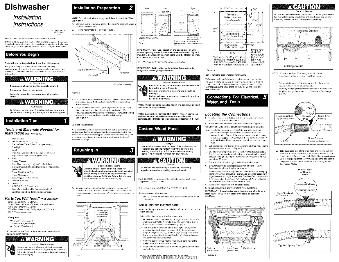
Dishwasher Installation Instructions Prnted n US A 154747401 10/10 INSTALLER: Leave Installation Instructionswith owner. OWNER: Read your dishwasher Use and Care Guide It contains important safety information for operating this appNance, n also has many suggestions for getting the best resuns from your dishwasher. Read all instructions before installing dishwasher. For your safety, please read and observe an safety instructions. This guide will help you anticipate drain, water, and electrical connections, and help you select the best location for the dishwasher. Tip Over Hazard Do not use dishwasher until completely installed. Do not push down on open door. Failure to follow this warning can result in serious injury. Cut Hazard To prevent serious injury from sharp edges, wear work gloves when handling, unpacking or disassembling unit, Tools and Materials Needed for Installation (Not Included) Ddll, Electric Ddver, Socket 5/32", '/4" ,5/," Flaring Tool / Tube Cutter (for copper tubing) Flashlight Level Pipe Joint Compound (for iron pipe plumbing) or Pipe Thread Tape (forseaNng threads) • Pliers Safety Glasses Saw, Keyhole or V2", 1V2" to 2" Hole Cutters Screw Drivers, Slotted and #2 Phillips (magnetic6p preferred) Tape, Electrical or Duct Tape, Measuring Wire Stripper or Utility Knife Wrench, Hex-end Ddll Bit Vs" # 32 Drill Bit (V_") (optional) Wrenches, 2AdjuWable (for copper tubing) or 2 Pipe wrenches (for iron pipe plumbing) Parts You Will Need* (NotIncluded) • Drain Hose Clamp, 1eg Diameter • Brass Elbow, 90' with a 3/d' National Pipe Thread • Conduit Connector (UL Listed) • Wire Nuts, three (3) for 12-14 gauge wire (UL Listed) • 2 # 7 V2" screws (optional) If required: • "Y"Branch Tailpiece and Connector Kit (See Step 4) • Air Gap Kit (See Step 4) All the parts can be found at local hardware, electrical and plumblng supply stores. NOTE: Put unit on its back being careful not to pinch the Water Drain Hose. 1. Remove two (2) screws at front of the kickplate assembly using a #2 Phillips screw driver. 2, Tilt and pull forward to remove see figure 1. WeigN: 12 Ibs. el_x, i_4u#:% h3_#et "!d + 114_:'/_" / 2 Pilot d_ill hc_eo* -/_1 (Vd' alia,_ _A" ma:_+de_th) *- 23 %,_" Kickplat6 Toeplate Figm"e3 i_suarl_ _L_ _YBECOMPaESSUEPOO_ IMPORTANT: For proper operation and appearance of unit, cabinet opening should have dimensions as shown in Figure 2, If unit is to be placed in a corner, there must be at least a 2-inch side clearance to open door. 2, FIoor should be flat and free of any obstruction. IMPORTANT: Drain, water, and electrical roughed-in before going any further. lines should be %- 6 Pilot drill fiole_ _-_I _| { %" dim a ¾" r3e;c de_,th) llot_: f_l h_odb efteeh r{leot _efeveT,fetlll_ be *0pfleoelholesfor eddie§1/2"- #7sore_s ltssh!feoes_,elf whichslipinto recta%olaf@eningoof belowp3nel me_31panteolhelp 17ocaotoestomdoor sg#lce L_ll_'/e pa#elfc_e#lerouts{descrew31techrneo_ i_tir_/uded,) Figure 4 ADJUSTING THE DOOR SPRINGS Kickplale ,-t _ _embly Before you push the dishwasher into the cabinet opening, test the door to make sure it stays in place at any angle. If it tends to fall down, pull out the machine and adjust the tension of the door springs on the sides of the machine by moving them one hole farther back. Figure 1 3. Locate water inlet valve behind kickplate on bottom left underside of unibSee Fig ure 4. The valve has a 3/8"NPT female rifting. Remove Plug 4. Wrap 90° elbow (not included) with pipe thread tape (or apply joint compound) and thread it into water inlet valve. When tightened, elbow should point toward the lee. To prevent bending of bracket or breaking of valve, avoid overlightening. See Figure 4. Cabinet Preoaration: As a precaution, it is recommended, but not required that the cabinets enclosing all sides of the dishwasher (including the underside of the countertop) be sealed with an oil based paint or moisture-proof polyurethane to prevent possible steamf moisture damage. NOTE: If dishwasher is installed at end of a cabinet, sides and back must be fully enclosed. NOTE: Cabinet Seal Kit (Kit # 154662101). This kit provides a seal between the unit and cabinets once installation is complete. (The Installation Instructions are located in the Kit) ! i ," _ k Weight Keep children away from the front of the dishwasher so that they are not accidentany hit by the door during loading or unloading or if door should unexpectedly open. The weight of the door can cause injury. electrical and plumbing connections, All electrical and plumbing work should be performed by q ua6fled persons. Failure to follow this warning could result in death or serious injury. Screws To prevent the posssibi6ty of corrosion, use factory supplied screws for mounting the wood panel, The EIDW6405HT can be installed with a fully integrated, buyer supplied custom door panel. 1. Make sure your location has the correct drain, water, and electrical outlets to make the connections. Do not instafl unit under a cooklop range. Damage to tub or other components will occur. k4 Figllre 2 The custom panel should be 1/2 to 3/4" (19mm) thick. Items provided with the unit: Six 1_/8"screws for moun0ng the custom wooden panel to the dishwasher. INSTALLING THE CUSTOM PANEL A custom door panel should be installed before the unit is mounted to the cabinet. Refer to the Figure 4 for instruction references. 1. Fit the handle onto the panel according to the manufacturer's instructions. (NOTE: A handle should be used rather than a knob. A knob does not provide enough grip.) 2. The two short screws (see Installation Tips, Parts you will need) go into the back of the panel 14W3_" from the upper edge of the panel and _/_" from the edge of the panel. Insert the short screws into the panel, leaving V_" of space between the screw head and the panel. 3. Hook the panel screws into the rectangular openings of the metal panel on the dishwasher door. 4. Open the door and use the six screws supplied to secure the panel to the door. NOTE: The door panel cannot exceed 12 pounds. Locating the Connections 1. Review dimensions in Figure 2 to locate dishwasher's drain, water, and electrical connections. 2, All utilities must be routed in shaded area in the Figure 2. IMPORTANT: Disconnect power before starting installation. Note: Locate the electrical supply and dishwasher's electrical junction box on right underside of unit behind kickplate assembly. See Figure 5. Determine where you will connect to hot water supply. Review Figure 5 and note the location of water inlet valve. Determine where you will connect the drain hose. 3. CutaccesshoiesfortheEiectdcaI, WaterandDrainhosesintbe shaded areas as shown in Figure 2, 4. The dishwasher operates on a 120 volt, 60 Hz electrical supply. Provide a separate circuit with a fuse or circuit breaker rated for at least 15 amps (20 amps if connected with disposer) but not more than 20 amps. 5. PUll electrical cable through hole into installation area. 6. Be sure water inlet valve is protected from freezing. If valve freezes and ruptures, flooding may occur. 7. Determine amot.mt of tubing needed to connect hot water supply to the uniPs water inlet valve. Extra hose length is necessary. High-pressure and high-temperature Stainless Flexible hose with a minimum inner diameter of '/g' may be used. A shut-off valve inWalled outside dishwasher cabinet is best. 8, Route water supply line intoinstalia6on area. 9. Stand dishwasher back updght for further instaliaOon. IMPORTANT: Incoming hot water least 120°F (49°C). Water pressure 20-90 psi, temperature should should be between be at (Not Included) Fig.re 5 Brass Elbow (Not Included) Electrical Line ! _ Ok Property Damage Do not use the furnished drain hose or a rubber garden hose for the water su pply line, Either of these hoses can burst, Flooding may occur and cause property damage. End Storage Location NOTE: Pull the hose from "End Storage Location" side. See images below to connect the Drain Hose. l. Take drain Hose out of dishwasher and find the end that doesn't have the black rubbe r material. 2. Use only the spring clamp that is provided in the accessory kit, place spring clamp over one of the hoses. See Image Below. Hose Attached To Dishwasher Hose Shipped Inside Dishwasher 3. Take the plastic side of the drain hose and insert it into the hose that is already attached to the dishwasher make sure hose ends are flush against each other. See image below. 4. Secure the spring clamp 1/8" from large end of black hose to the plastic side that was inserted for best sealing resuns. See Image Below. Plastic Ends of Hoses Flush Hose Attached Tighten Spring Clamp
-
 1
1 -
 2
2
 |
 |