Electrolux EIDW6405HT Installation Instructions - Page 2
Dishwasher, Anchoring, Electrical, check, these, items, Operate, through, the following - reviews
 |
UPC - 012505111464
View all Electrolux EIDW6405HT manuals
Add to My Manuals
Save this manual to your list of manuals |
Page 2 highlights
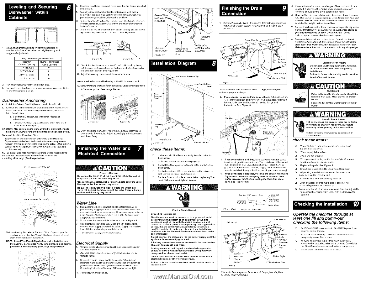
1. Measure height of cabinetopening from underside of countertop tofloor. Check chartfor height opening and suggested adjustment. Leg Leveler Adjustment Chart Heightof Cabinet Opening Number of Tumsto Adjust Levelers 34"(86.4cm) 0 34 _8"(86.7cm) 2 34 _" (87.2cm) 6 34_z"(87.6cm) 9 2, Move dishwasher to front of installation area. 3. Loosen the rear ]evefing legs by turning counterclockwise. to chart for number of turns. Refer Dishwasher Anchoring 4. instal] the Cabinet Seal Kit (Instn.lctions included in Kit) 5. Choose one of the methods of attachment below to secure unib holes need to be pre-ddlled using a #5 ddll bit regardless of the option chosen: a. Side Mount Cabinet Clips (Preferred Method of attachment) b. Top Mount Cabinet Clips (to be used when Side Mount is not an available option) CAUTION: Use extreme care in mounting the dishwasher as to not scratch, bump or otherwise damage the console or tub. To install the Side Mounting Clips, Depending on space allowed in cabinet the Side Mounting Clips can be installed with the holes for the screw Lip (preferred method) or down as shown in the illustrations below. (Use extreme caution when the dips are in the down position while installing the dishwasher). NOTE: Install Side Mount Brackets before unit is installed into the cabinet. Insert screws intothe front holes of the mounting clips only. (See image below) Use {f measures 341/_ '' to 35" Use if measu,_s 34" to 34V_" TO install using Top Mou nt Cabinet Clips: Depending on the depth of cabineb the Top Mount Clip have a break off point that can be removed if necessary. NOTE: Install Top Mount Clips before unit is installed into the cabinet. Screw clips flrrnly to top brace using screws provided in the literature pack. (See image below) 6, If levelers need to be removed, make sure that the floor is free of all obstr_lcfions. 7. Care fully place dishwasher inside cabinet area such that is centered in opening. Use caution when moving dishwasher to prevent damage to cabinet, dishwasher and floor. 8. Front of door needs to be even with the front of adjoining cabinets. Front levelers ShOLddallow 5/16" below underside of countertop to top of console. 9. Check that dishwasher is level from side to side by placing a level against the top front section of the tub. See Figure 6a. 10. Check that the dishwasher is level from front to back by taking out the lower rack, place level on the lower rack wheel support at the bottom of the tub. See Figure 6b. 11. Adjust levelers Lip or down until dishwasher is level. Holes need to be pre-drified using a #5 drill to secure unit. 12. Screw mounting brackets firmly to cabinet using screws provided in literature packet. See Image Below. Junction Box Cover Figm'e 7a Wire to Black Wire (Hot) Box White Wire to White Wire (Neutral) 1. Review Figures 8, 9 and 10 to see the different ways to connect dishwasher to drain system. Choose method that best suits yourneed. 5. [fthe cabinet wall is wood, sand edges of hole until smooth and rounded. If cabinet wall is metal, cover all sharp edges with eleclrical or duct tape to avoid cutting drain hose. Move unit back in place while routing drain hose through access hole. Use caution to prevent damage to the dishwasher, floor and cabinets. IMPORTANT: Make sure there are no sharp bends or kinks that might restrict drain flow. Secure drain hose to sink drain, disposer, or separate trap with a clamp. IMPORTANT: Be careful not to overtighten clamp or you may damage end of hose. Do not connect hose to horizontal pipe between sink drain and disposer. Be sure unit does not rest on drain hose. I_should be free of electrical components and door spnngs. Do not cut corrugated drain hose. PLdl excess through cabinet and place under sink. Make sure hose does not come in contact with any sharp edges. Jf Sink ,t L_# Sink at R_h, F_.re 8 The drain hose h)op mu_t be at least 32" high [rom the [Ioor to insuraproper draimtga, 2, If you connect to a sink drain, entry will need to be above trap. A "Y" branch tailpiece and connector kit, not included, will make this method easier and includes all needed fillings and instructions. See Figure 8. Electric Shock Hazard Disconnect electrical power at the fuse box or circuit breaker box before beginning installation. Failure to follow this warning could result in death or serious injury. Failure injury. to follow this warning may result in Figztre 6c Figttre 6d 13. Open and close dishwasher door slowly. Ensure that there is clearance to the console. Adjust accordingly unfil door opens and closes freely. Property Damage Do not solder within 6" of the water inlet valve. Damage to the plastic parts in the valve may occur. Use care that no sealer, dirt, or other objects enter the valve. Damage to the filter screen may occur. Be sure the dishwasher is placed where the water inlet valve will be kept from freezing. If the valve freezes, it may rupture and flooding may occur. Water Line 1, FlUsh water line before connecting it towater inlet valve to prevent early clogging of filter screen. Place a bunched towel over end of line to prevent splashing. Open water supply valve for a few seconds and let water drain into a pan. Turn off water supply at shut-off valve. 2. Rot.de water line to water inlet valve as shown in Figure 5. 3. While firmly pulling water supply line into 90 ° elbow, tightly connect water supply to water inlel valve. Supply line must be free of kinks, scales, chips, and lubricants. 4. Turn on water supply and check for leaks. Electrical Supply 1. Remove junction box cover and pui] house widng into junction box. See Figure 7a. 2, Use a UL listed conduit connector (not included) at box to stabilize wiring. 3. Connect incoming black lead to dishwasher's black lead, incoming white lead to dishwasher's white lead and incoming green lead to dishwasher's green lead with wire nuts. (See Grounding Instruction Warning). Wire nuts must be tight. 4. Replace junction box cover. Figure 71) check these items: Water and electrical lines are straight out in front of the dishwasher. All four leg levelers are positioned properly. Cabinet Seals are positioned on the sides and top of the dishwasher. Cabinet Attachment Clips are attached to the cabinet on both comers on top of the dishwasher. Replace Toe and Kickplate. Note: When replacing Toe and Kickplate hand tighten screws. check these items: 3. If you connect to a sink trap, local codes may require you to install an air gap kit, (not included). The drain hose will be routed from dishwasher to air gap inlet as shown in Fig ure 9. An air gap kit is available from a plumbing supply store. (If the drain hose is installed through the floor, an air gap is necessary). 4. If you connect to a disposer, the large end of drain hose will fit. Fig ure 10(a). The knock out plug must be removed from inside disposer inlet before making the final fit to drain hose See Figure 10(b). Water and drain lines have no kinks and move freely behindthe dishwasher. Water supply is turned on. Joints are free of leaks. Wiring connections to junction box are tight all access panels are secured back in place. Replace kickplate. See Figure 1 Drain hose is assembled to Drain Hose Connector. All packing materials and consumer literature have been removed from inside unit. Dishwasher is level and securely fastened. Open and dose door to make sure it does not hit surrounding cabinet or countertop. Make sure that all wire ties are removed from the Adjustable Rack Assembly, Versa Tray, Utility Tray and Silverware Baskets. Electric Shock Hazard Grounding Instructions: The dishwasher must be connected to a grounded metal, permanent wiring system or an equipment-grounding conductor must be run with the circuit conductors and connected to the appliance's equipment grounding terminal or lead. ]t is the consumer's responsibility to contact a qualified installer to make sure the electrical installation conforms with the National Electrical Code and local codes and ordinances. Do not connect the dishwasher to the power supply until the appliance is permanently grounded. All wiring connections must be enclosed in the junction box. This unit has copper lead wires. Joining aluminum building wire to stranded copper wire should be done by a qualified electrician using materials recognized by UL and local codes. Do not use an extension cord. Such use can result in fire, electrical shock, or other personal injury. Failure to follow these instructions serious injury. could res ult in death or Figttre lOpO / Cuth_t 3/4"_,mne_tion, Sink at Le# C _\ _ "_a_a_tit Gap '" _D " 109(b) The drain hose h)op mu_t be at h,a_t 32" high [rom the [loor to insm'e proper _'ainag_ Operate the machine through at least one fill and pump-out, checking the following items: On EIDW6405HT press and hold SANITIZE keypad for 8 seconds before first use. At first fill, approximately 2 minLdes, make sure water completely covers filter surface. At pump-ouh (pump_ut is either when the cycle is completed or canceled, refer to the Use and Care Guide for Stad/Cancel), make sure all water is pumped ouk Check water connections again for leaks.
-
 1
1 -
 2
2
 |
 |