Electrolux EW30GC60IS Installation Instructions (All Languages) - Page 9
When All Hookups are Complete, Before You Call for Service - lowes
 |
UPC - 057112103624
View all Electrolux EW30GC60IS manuals
Add to My Manuals
Save this manual to your list of manuals |
Page 9 highlights
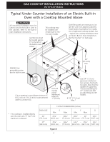
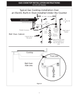
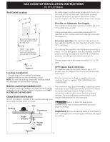
GAS COOKTOP INSTALLATION INSTRUCTIONS (For 30" & 36" Models) 2. Turn on Electrical Power and Open Main Shutoff Gas Valve 3. Check the Igniters Operation of electric igniters should be checked after cooktop and supply line connectors have been carefully checked for leaks and the cooktop has been connected to electric power. To operate the surface burner: A. Push in and turn a surface burner knob to the LITE position. You will hear a small ticking noise; this is the sound of the electric ignitor which lights the burner. B. After the burner lights, turn to the desired flame size. The controls do not have to be set at a particular mark. Use the marks as a guide and adjust the flame as needed. 4. Adjust the "low" setting for regular surface burner valves (Figure 12) Be careful when performing this operation. a. Push in and turn control to LITE until burner ignites. b. Quickly turn knob to LOWEST POSITION. c. If burner goes out, reset control to OFF. d. Remove the surface burner control knob. e. Insert a thin-bladed screwdriver into the hollow valve stem and engage the slotted screw inside. Flame size can be increased or decreased with the turn of the screw. Turn counterclockwise to increase flame size. Turn clockwise to decrease flame size. Adjust flame until you can quickly turn knob from LITE to LOWEST POSITION without extinguishing the flame. Flame should be as small as possible without going out. Note: Air mixture adjustment is not required on surface burners. 5. Adjust the "LOW" Setting of the Dual Burner Surface Valve (Figure 12) Note: On the dual valve the low setting of each portion should be adjusted individually. a. Push in and turn control to LITE until the rear portion of the bridge burner ignites only. b. Quickly turn knob to LOWEST POSITION. c. If burner goes out, reset control to OFF. d. Remove the surface burner control knob. e. The rear or outer portion of the burner flame size can be increased or decreased with the turn of the screw A. Use screw B to adjust the flame size of the center portion of the burner. Turn counterclockwise the screw to increase flame size. Turn clockwise the screw to decrease flame size. Adjust flame until you can quickly turn knob from LITE to LOWEST POSITION without extinguishing the flame. Flame should be as small as possible without going out. Note: Air mixture adjustment is not required on surface burners. Clockwise Counterclockwise A Hollow Valve Stem B Regular Burner Valve Dual Valve Figure 12 When All Hookups are Complete Make sure all controls are left in the OFF position. Make sure the flow of combustion and ventilation air to the cooktop is unobstructed. Before You Call for Service Read the Before You Call for Service Checklist and operating instructions in your Use and Care Guide. It may save you time and expense. The list includes common occurrences that are not the result of defective workmanship or materials in this appliance. Refer to the warranty in your Use and Care Guide for our service phone number and address. Please call or write if you have inquiries about your product and/or need to order parts. 9
-
 1
1 -
2
-
3
-
 4
4 -
 5
5 -
 6
6 -
 7
7 -
 8
8 -
 9
9 -
 10
10 -
 11
11 -
 12
12 -
 13
13 -
 14
14 -
15
-
16
-
17
-
18
-
19
-
20
-
21
-
22
-
23
-
24
-
25
-
26
-
27
-
28
 |
 |
