Electrolux FMV156DS Installation Instructions - Page 5
Ventilation System, Oven Installation
 |
View all Electrolux FMV156DS manuals
Add to My Manuals
Save this manual to your list of manuals |
Page 5 highlights
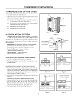
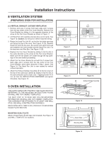
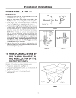
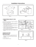
Installation Instructions 8 VENTILATION SYSTEM (PREPARING OVEN FOR INSTALLATION) (C) VERTICAL EXHAUST: OUTSIDE VENTILATION 1. Remove and save 2 screws from back edge and 3 screws from the top center of the Fan Cover Bracket. Remove Fan Cover Bracket by sliding it in the opposite direction of the arrow on the Fan Cover Bracket as shown in Figure 11. 2. Lift Hood Fan Unit carefully and slip wires out of cavity. See Figure 12. Caution: Do not pull or stretch hood fan wiring. 3. Rotate the Hood Fan Unit 90˚ so that the fan blade openings are facing the top of the oven. See Figure 13 (A). Replace Hood Fan Unit into the oven. Be careful not to pinch the lead wire between the inner bracket and the Hood Fan Unit. Put the lead wire into Wire Box. See Figure 13 (B). 4. Replace the Fan Cover Bracket by sliding it into the slits in the same direction as the arrow on the Fan Cover Bracket. Make sure the fan blades are visible through the top openings in the oven before proceeding. 5. Attach the Fan Cover Bracket to unit with the 2 screws from back edge and 3 screws from the top center of the Fan Cover Bracket, which were removed in Step 1 above. See Figure 14. The Hood Fan Unit is now rotated for vertical exhaust operation. 6. Attach the Exhaust Damper Assembly 9 to the fan cover on the top of the outercase cabinet by sliding it into the slits in the same direction as the arrow. Use 1 Tapping Screw 4 X12 mm 5 from the INSTALLATION HARDWARE and tighten into place. See Figure 15. Figure 11 (B) (A) Rotate 190˚ Figure 13 Figure 12 Figure 14 Exhaust Damper Assembly 9 OVEN INSTALLATION THIS OVEN CANNOT BE PROPERLY INSTALLED WITHOUT REFERRING TO THE MOUNTING INSTRUCTIONS FOUND ON WALL AND TOP CABINET TEMPLATES. THE NEXT STEP IS TO READ AND FOLLOW MOUNTING INFORMATION ON WALL AND TOP CABINET TEMPLATES. THIS OVEN MUST BE ATTACHED TO AT LEAST ONE WALL STUD. SEE WALL CONSTRUCTION ON PAGE 6. WHEN DONE WITH TEMPLATES, PROCEED TO MOUNTING SCALE PLATE SECTION. Figure 15 MOUNTING SCALE PLATE Attach 2 Scale Plates ! with tape (not included). See Figure 16 and WALL TEMPLATE for locations. Scale Plates Mounting Plate Figure 16 5
-
 1
1 -
 2
2 -
 3
3 -
 4
4 -
 5
5 -
 6
6 -
 7
7 -
 8
8
 |
 |
