Epson ActionNote 4000 Product Information Guide - Page 4
External Connector Pin Assignments, ActionNote 4000-4
 |
View all Epson ActionNote 4000 manuals
Add to My Manuals
Save this manual to your list of manuals |
Page 4 highlights
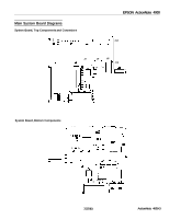
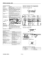
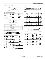
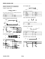
EPSON ActionNote 4000 System Board Components Component CPU (U1) BTC-5001 (U2) 80C42/8742 (U4) DS 1287 or compatible RTC (U5) TH6460 (U7) DRAM (U13, U14, U8, U9) DB86082 (U10) ACC 2036 (U12) Description 486SLC/33 microprocessor: 1KB internal, two-way set associative cache BTC keyboard encoder&coder (70C40/77C82) integrated, 8042 compatible, keyboard controller Dallas DS 1287 or compatible RTC; includes Lithium backup battery and RAM Peripheral controller; provides one printer parallel port, two 16450 UARTS, IDE HDD interface, FDC, bus interface buffers 4MB standard memory, 2MB soldered on main system board and one 2MB memory module; expandable to 8MB by replacing the 2MB memory module with a 8MB memory module (J5) DataBook PCMCIA controller and driver interface I module System controller; provides AT bus control logic. External Connector Pin Assignments Parallel Port Connector (J3) pin 13 pin 1 pin 14 Parallel Port Connector Pin Assignments F Signal Pin (Parallel) 1 /STROB (Strobe) 2 I Data 0 3 I Data 1 Signal (FDD) Not connected Signal Pin (Parallel) 14 /AUTOFD 1 Index 1 Read data 15 /ERROR 16 1 /INlT Signal (FDD) Reduce write current 1 1 Head select I Direction (U27, U28, U35) ACC 2020 (U29) AM27C010 (U30) Buzzer (BZ1) Power management controller 1024 Kb (128 Kb x 8) (OT) EPROM; VGA BIOS ROM and Initialization BIOS ROM used during power up; Databook Socket Services; supports shadow RAM Internal System Board Connectors Connector I Description Keyboard or mouse (J1) 1 6-pin, mini-DIN, female (back panel) Cover switch (J2) ] P-pin header, mate Parallel port, printer/external FDD (J3) 1 25-pin, D-shell, female (back panel) PCMCIA (J4) 68-pin header, male Memory module (J5) 44-pin header, female Serial port, COM1 (J6) 9-pin, D-shell, male (back panel) Keyboard ribbon cables (J7, J9) Ribbon terminators, 8-pin and 16-pin, respectively IDE HDD (J8) 50-pin edge connector; female, supports HDD External CRT VGA (J11) 15-pin female, back panel CCFT inverter, LCD backlight, brightness/contrast (J12) LCD panel (J13) I12-pin header, male I B-pin header, male LED (J14) 10-pin header, male Trackball (J15) 4-pin header, male Power supply, DC-DC converter (J16) 22-pin connector, female; supplies power from the power supply to the main system board 12 1 Paper end 1 Write data 125 1 Ground I Ground I 13 1 SLCT I Write enable I Serial Port Connector (J6) Serial Port Connector Pin Assignments Keyboard/Mouse Connector CJ1) pin 6 pin 5 pin 4 pin 3 pin 2 pin 1 Keyboard/Mouse Connector Pin Assignments Pin Signal 1 Mouse data 2 Keyboard data 3 Ground Pin Signal 4 +5 VCC 5 Clock, mouse 6 Clock, keyboard ActionNote 4000-4 7/27/93
-
 1
1 -
 2
2 -
 3
3 -
 4
4 -
 5
5 -
 6
6 -
 7
7 -
 8
8 -
 9
9
 |
 |
