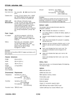
Epson ActionNote 4000 Product Information Guide - Page 7
DMA Assignments, Hardware Interrupts, System l/O Address Map, Hard Disk Drive Types
 |
View all Epson ActionNote 4000 manuals
Add to My Manuals
Save this manual to your list of manuals |
Page 7 highlights
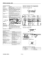
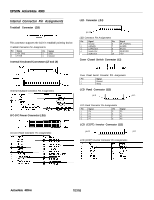
DMA Assignments Level DMA0 DMA1 DMA2 DMA3 DMA4 DMA5 DMA6 DMA7 Assigned Device Available Available FDD controller (8-bit) Available Cascade for CTRL 1 Available Available Available Hardware Interrupts IRQ No. IRQ0 IRQ1 IRQ2 IRQ3 Function System timer Keyboard cascade COM2 (trackball) IRQ5 IRQ6 IRQ7 IRQ8 IRQ9 IRQ10 IRQ11 IRQ12 IRQ13 IRQ14 IRQ15 Available FDD controller Parallel port LPT1 Clock/calendar VGA Available Available PS/2 compatible mouse Resewed for numeric coprocessor HDD controller Available System l/O Address Map Hex Address 000-020 020-040 040-060 060-070 070-080 080-0A0 0A0-0C0 0C0-0F0 I Assigned Device 1 DMA controller 1 I Interrupt controller Timer/counter Keyboard controller Real-time clock NM1 (non-maskable interrupt mask) DMA page register I Interrupt controller 2 I DMA controller 2 EPSON ActionNote 4000 Hard Disk Drive Types * Actual size when formatted may be slightly different than the size listed on the drive label. ** Epson hard disk drive Programmable Timer/Counters Power-On Diagnostics and Boot Errors The computer's ROM BIOS contains a series of diagnostic programs, called the Power-On Diagnostics (POD) or Power-On Self Test (POST). These programs check internal devices, such as ROM, RAM, the timer, the keyboard controller, and the hard disk drive, every time you turn on or reset the computer. When the POD tests detect an error, the computer displays a message on the screen. (If the error occurs before the computer initializes the video display, the computer beeps.) If the error is serious, the computer cancels further checking and stops system initialization. The computer locks up, and if displayed, the error message remains on the screen. The table below lists the error messages that may appear. The solutions provided must be followed in order. If more than one replacement module is specified, replace them in order, one at a time. Power-on Diagnostics Error Messages Error No. 1 2 3 4 Message CMOS Battery Has Failed CMOS Checksum Error Explanation Battery in DS 1287 or compatible RTC that supports CMOS is low. Replace DS 1287 or compatible RTC. Checksum of CMOS is incorrect. This can indicate that CMOS is corrupted; it may be caused by a weak battery. Check battery and replace DS 1287 or compatible RTC if necessary. Interrupt channel #2 failed POD routine. Battery in DS 1287 or compattible RTC that supports CMOS is low. Replace DS 1287 or compatible RTC. 7/27/93 ActionNote 4000-7
-
 1
1 -
 2
2 -
 3
3 -
 4
4 -
 5
5 -
 6
6 -
 7
7 -
 8
8 -
 9
9
 |
 |
