Epson ActionNote 880 Product Information Guide - Page 5
Connector Pin Assignments
 |
View all Epson ActionNote 880 manuals
Add to My Manuals
Save this manual to your list of manuals |
Page 5 highlights
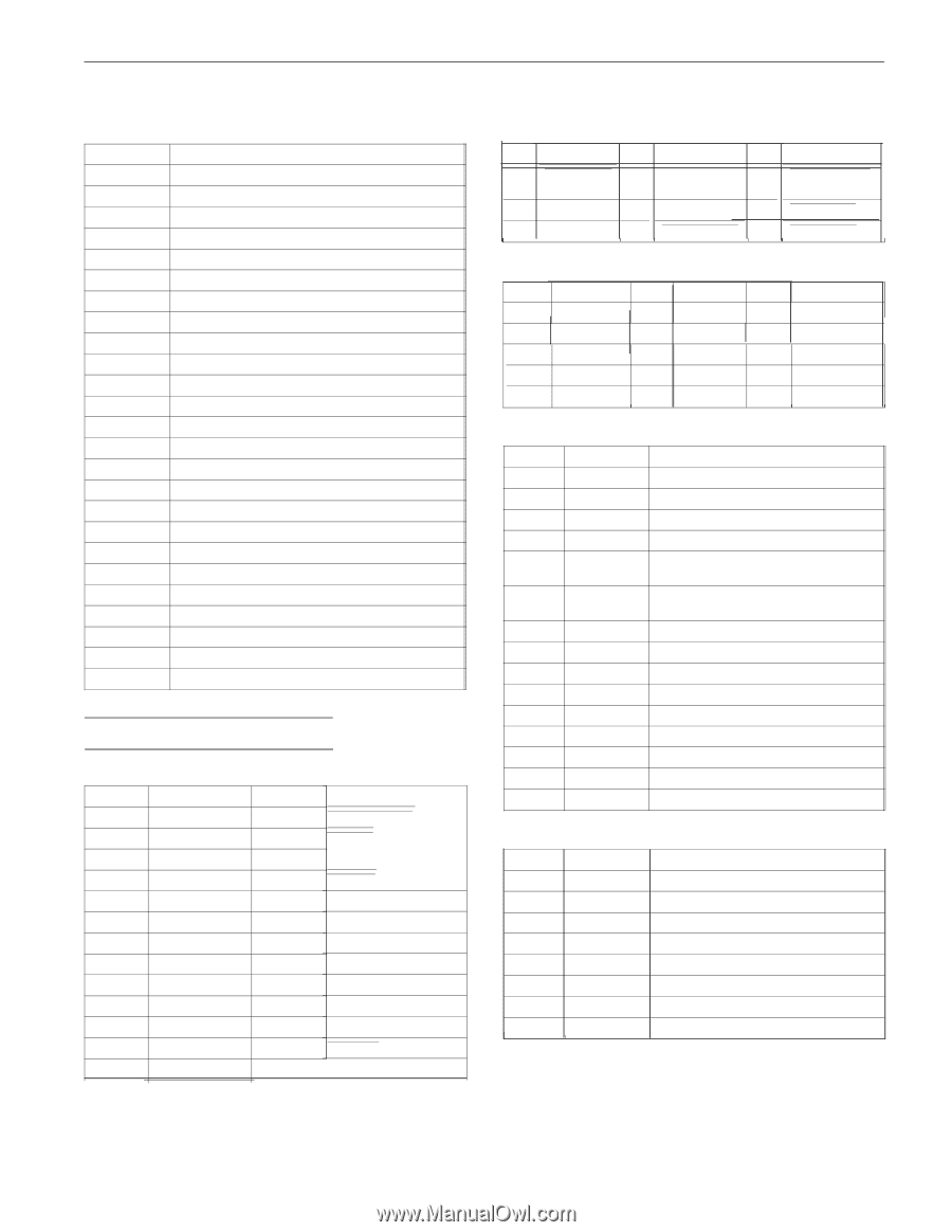
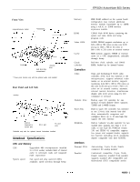
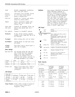
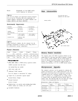
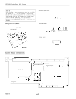
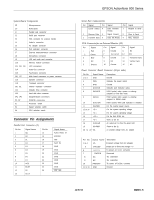
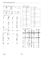
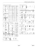
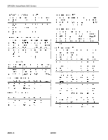
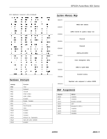
System Board Components U4 Microprocessor U6 ROM BIOS Ji Parallel pod connector J2 Serial port connector J3 VGA connector for external monitor J4 Audio-In connector J5 AC adapter connector J6 Port replicator connector J7 External keyboard/mouse connector J8 Microphone connector J9 LED and audio card connector J10 Memory module connector J11, J12, J13 J14 J15 J16, J17 J18 J19 J20, J21 J22 LCD connectors Audio-Out connector Fax/modem connector Main board connectors to power converter Speaker connector Trackpad connector Internal keyboard connectors Diskette drive connector J23 JP1, JP2 P1, P2 S1 S2 S4 Hard disk drive connector Daughterboard connectors PCMCIA connectors Processor switch Speed selection switch CPU selection switch Connector Pin Assignments Parallel Port Connector (J1) Pin No. 1 2 3 4 5 6 7 8 9 10 11 12 13 Signal Name NC DO D1 D2 D3 D4 D5 D6 D7 ACK BUSY PE SLCT Pin No. 14 15 16 17 18 19 20 21 22 23 24 25 Signal Name AUTO FEED XT ERROR INIT SLCT IN GND GND GND GND GND GND GND PRT SEL EPSON ActionNote 800 Series Serial Port Connector(J2) Pin Signal Pin Signal Pin Signal Carrier Detect 4 Data Terminal 7 Ready Request to Send 2 Receive Data 5 Signal Ground 8 Clear to Send 3 Transmit Data 6 Data Set Ready 9 Ring Indicator VGA Connectorfor an External Monitor (J3) Pin Signal 1 Red 2 Green 3 Blue 4 NC 5 Ground Pin Signal Pin 6 Ground 11 7 Ground 12 8 Ground 13 9 NC 14 10 Ground 15 Signal NC NC I Horizontal Sync Vertical Sync NC Power Converter Board Connector (22-pin male) Pin No. 1 to 4 5 6 7 8 Signal Name GND PSW GND DOCKON SUSHDD 9 SUSCH 10 DOCKSW 11 INVPWR 12 to 14 +5 v 15 +3 v 16 +12 v 17 +3 v 18 CHGLED 19 INVPWR 20 to 22 VA Description Ground Indicates the power switch Ground Indicates port replicator status HIGH (active) when system is entering suspend to hard disk mode HIGH (active) when system is entering suspend to DRAM mode HIGH (active) when pod replicator is installed For the inverter power source For the system operating voltage For the system operating voltage For the flash ROM, etc. Same as pin 15 An output pin to drive the green LED Same as pin 11 A constant voltage form AC adapter Pin No. Signal Name Description 1 to 4 VA Constant voltage from AC adapter 5 CHGLED Output pin to drive the orange LED 6 SWITCH To power on DC/DC converter 7 PWRON Reserved 8 NC No connection 9 NC No connection 10 PWROFF To bower off DC/DC converter 11 to 14 GND Ground I 12/9/94 AN800-5
-
 1
1 -
 2
2 -
 3
3 -
 4
4 -
 5
5 -
 6
6 -
 7
7 -
 8
8 -
 9
9 -
 10
10
 |
 |