Epson C107001 Product Information Guide - Page 5
Interface Specifications - lq 570 paper
 |
UPC - 010343157507
View all Epson C107001 manuals
Add to My Manuals
Save this manual to your list of manuals |
Page 5 highlights
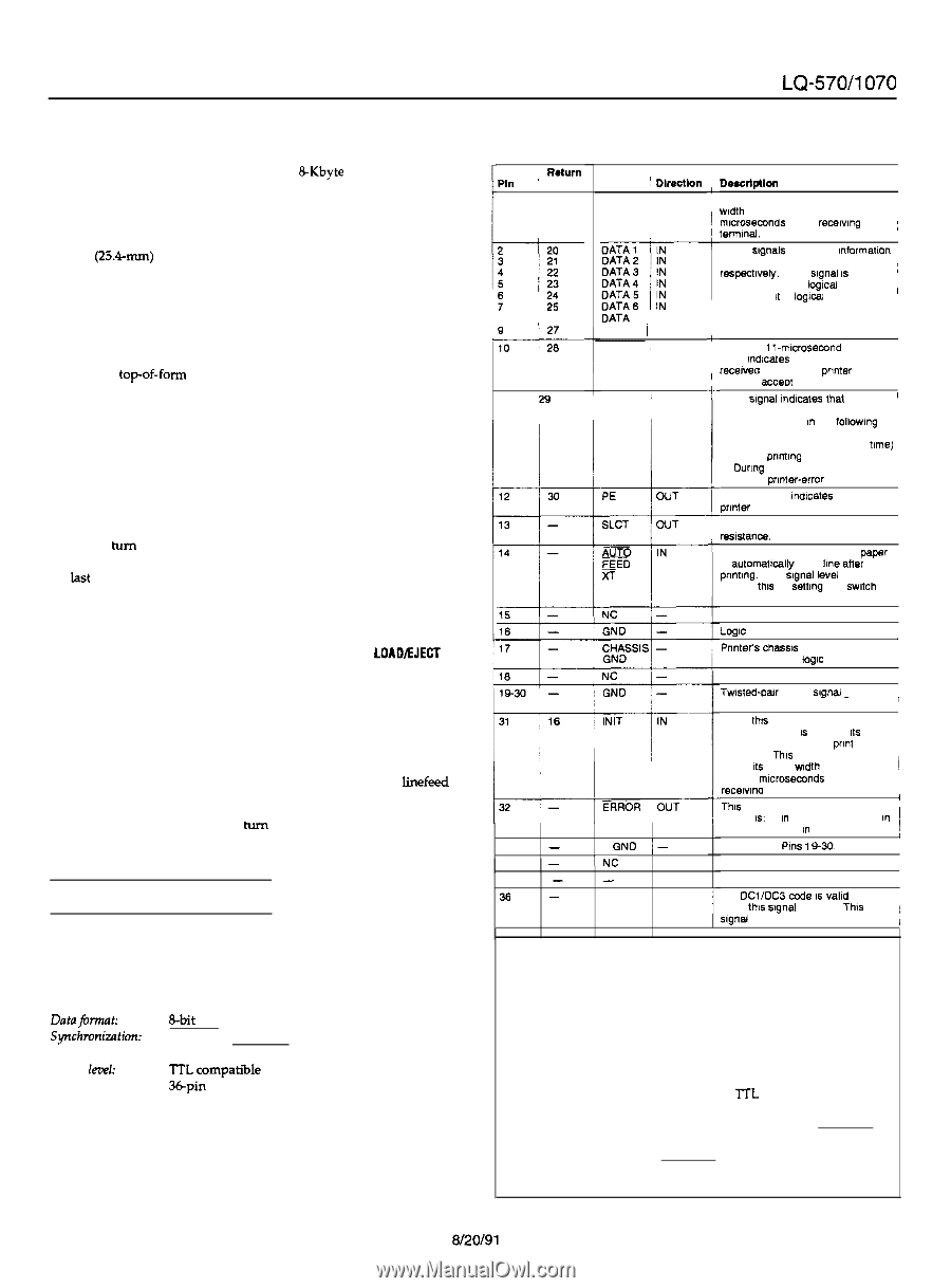
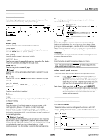
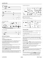
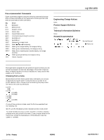
Input buffer capacity The printer stores print data sent from your computer in its input buffer. Keep DIP switch 1-7 off to select an BKbyte buffer. Skip-over-perforation Turning DIP switch 1-8 on when you are using continuous paper enables the skipover-perforation function Use this function to leave a l-inch (25.~mm) margin between the last printable line on one page and the first printable line on the next page. This causes the printer to skip over the perforation between continuous sheets. Most application programs take care of the top and bottom margins. Do not turn on skipover-perforation unless your program does not provide these margins. Adjust your topof-form position with the MICRO FEED buttons to get half of the margin at the bottom of one page and half at the top of the next page. Continuous paper page length When you are printing on continuous paper, DIP switches 2-l and 2-2 let you select from the four page lengths described in DIP-switch Table 5. Tear off When you turn DIP switch 2-3 on, the tear-off feature is automatic when using continuous paper. The printer automatically advances the last printed page to the tear-off position. You can then easily tear off the printed paper. The printer automatically returns the paper to the loading position when it receives more print data. You can also return the paper to the loading position by pressing the TEAR OFF button or the LOAD/EJECT button Use the tear-off feature only with continuous paper loaded with the push tractor. Do not use the tear-off feature with the pull tractor. Auto line feed When auto line feed is on (DIP switch 2-4 on), the printer accompanies each carriage-return code (CR) received with a linefeed code (LF). lf your printer is double spacing, turn DIP switch 2-4 off. If each line overprints the next, turn DIP switch 2-4 on Interface Specifications Your printer is equipped with a parallel interface. Specifications and pin assignments The built-in parallel interface has the following characteristics: Datafbrmat: Synch7unization: Handshake timing: Signal level: Connector: Bpbaitr a l l e l STROBE pulse BUSY and ACKNLG signal ITL compati%le level 36pin 57-30360 (Amphenol) connector or equivalent LQ-570/1070 Connector pin assignments and a description of their respective interface signals are shown in the following table. Signal ' Return Pin ) Pln 1 i 19 ---i--Y20 : 4 i: 5 23 !6 !7 E 8 26 Lii---k 11 29 Signal ! DIrectIon STROBE 1IN cDeSCrlplloll STROBE pulse to read data. Pulse width must be more than 0.5 1 mlcroseamds at the recalvmg ~ termmal. cThese slgnais represent mformatlon , of the 1st to 8th bits of parallel data, i respectively. Each slgnal IS at HIGH , level when data IS loglcal 1 and LOW when It IS logxal 0. I CATA 7 I IN DATA8 / IN ACKNLG / OUT I BUSY ( OUT + About an 11-mlcrosewnd pulse LOW mdlcates that data has been j/I-rrHpeerIcaiGnedtiHvevertsdoclgaanancanncldoemtnthtdraelcmtcaetothierveesepddtrhamaattattae..rthTeIShe I 1 signal goes HIGH In the followmg i cases: 1) During data entry (ea. char. time) ; 2) During pnntmg 3) Ounng PAUSE c4) During pnnter-error state A HIGH signal mdlcates that the / cprmter IS out of paper. Pulled up to 5V through 3.3 Kohm tWhen this signal IS LOW, the paper IS automattcallv fed 1 lme atler pnntmg. (The ilgnal lzvel can be fixed to this by settmg DIP switch 24 to ON.) t Not used Logic ground level. J Pnnter's chassis ground, which IS I iisolated from the logic ground. : Not used. Twlsted-oar return sia- nal -around level. II 33 - ! GND j- When thts level becomes LOW, the I printer controller IS reset to Its I power-up slate and the pnnt buffer 1 IS cleared. This level IS normally HIGH; Its pulse width must be more 1 than 50 mlcroseconds at the recelvma terminal. iI t-Tphriinsteler v1es:l becomes LOW 1) m paper out when state, the 2) In j PAUSE state, 3) m error state I I Same as for Pms 1 Q-30 34 - INC I- I Not used. 35 - - OUT I Pulled up to 5V through 3.3 Kohm 36 - SLCT IN IN ' The DCl/DCJ cede IS valid only 1 when this slgnal IS HIGH This 1 , slgnal IS always LOW / Note: l The column heading "Direction" refers to the direction of signal flow as viewed from the printer. l "Return" denotes the twisted-pair return, to be connected at signal ground level. For the interface wiring, be sure to use a twisted-pair cable for each signal and to complete the connection on the return side. l All interface conditions are based on TTL level. Both the rise and fall times of each signal must be less than 0.2 microseconds. l Data transfer must be carried out by observing the ACKNLG or BUSY signal. (Data transfer to this printer can be carried out only after receipt of the ACKNLG signal or when the level of the BUSY signal is LOW.) 24-Pin Printers LQ-570/1070-5
-
 1
1 -
 2
2 -
 3
3 -
 4
4 -
 5
5 -
 6
6 -
 7
7
 |
 |