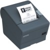
Epson C31CA85090 User Manual - Page 5
DIP Switch Tables, Specifications, DIP switch 2-7, 2-8 Parallel/USB Interface
 |
View all Epson C31CA85090 manuals
Add to My Manuals
Save this manual to your list of manuals |
Page 5 highlights
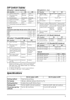
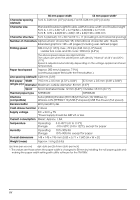
English DIP Switch Tables DIP switch 1 (Serial Interface) SW Function ON 1-1 Data receive error Ignored 1-2 Receive buffer capacity 45 bytes 1-3 Handshaking XON/XOFF 1-4 Data word length 7 bits 1-5 Parity check Enabled 1-6 Parity selection Even 1-7 Transmission speed (See table A.) 1-8 OFF Prints "?" 4K bytes DTR/DSR 8 bits Disabled Odd Table A Transmission speed (bps)-bits per second SW1-7 SW1-8 38400*1 ON ON 4800 OFF ON 9600 ON OFF 19200 OFF OFF DIP switch 1 (Parallel/USB Interface) SW Function ON 1-1 Auto line feed Always enabled 1-2 Receive buffer capacity 45 bytes 1-3*2 Select paper sensors Disabled to output paper-end signals (default value of a command) from parallel I/F. 1-4*2 Error signal output from parallel I/F Disabled 1-5~ 1-7 Undefined 1-8*3 Power saving function Disabled for USB OFF Always disabled 4K bytes Roll Paper end sensor enabled, Roll Paper nearend sensor enabled Enabled Enabled *1: When DIP Switches 1-7 and 1-8 are on, the transmission speed can be selected from one of seven speeds: 2400, 4800, 9600, 19200, 38400, 57600, and 115200 bps by control commands. *2: For USB I/F, DIP Switches 1-3 and 1-4 are Undefined. *3: For Parallel I/F, DIP Switch 1-8 is Undefined. DIP switch 2-1~ 2-6 SW Function ON OFF 2-1 Handshaking (BUSY condition) Receive buffer Offline or full Receive buffer full 2-2 Do not change settings Fixed to OFF 2-3 Print density 2-4 See Table B 2-5 Release condition of Releases BUSY Releases BUSY receive buffer BUSY when remaining when remaining (If receive buffer receive buffer receive buffer capacity set to 4 KB.) capacity capacity reaches reaches 138 bytes. 256 bytes. 2-6 Do not change settings. Fixed to OFF DIP switch 2-7, 2-8 (Serial Interface) SW Function 2-7 I/F pin 6 reset 2-8 I/F pin 25 reset ON Enabled Enabled OFF Disabled Disabled DIP switch 2-7, 2-8 (Parallel/USB Interface) SW Function 2-7 Do not change 2-8 Do not change ON OFF Fixed to OFF Fixed to ON Table B Print density/low power Print density "Normal" Print density "Medium" Print density "Dark" Do not set SW2-3 OFF ON OFF ON SW2-4 OFF OFF ON ON Specifications Printing method Dot density Printing direction Printing width Characters per line (default) 80 mm paper width 58 mm paper width* Thermal line printing 180 dpi ×180 dpi [dots per 25.4 mm {1"}] Unidirectional with friction feed 72 mm {2.83"}, 512 dot positions 50.8 mm {2.0"}, 360 dot positions Font A: 42; Font B: 56 Font A: 30; Font B: 40 v
-
 1
1 -
 2
2 -
 3
3 -
 4
4 -
 5
5 -
 6
6 -
 7
7 -
 8
8 -
 9
9 -
 10
10 -
 11
11 -
12
-
13
-
14
-
15
-
16
-
17
-
18
-
19
-
20
-
21
-
22
-
23
-
24
-
25
-
26
-
27
-
28
-
29
-
30
-
31
-
32
-
33
-
34
-
35
-
36
-
37
-
38
-
39
-
40
-
41
-
42
-
43
-
44
-
45
-
46
-
47
-
48
-
49
-
50
-
51
-
52
-
53
-
54
-
55
-
56
-
57
-
58
-
59
-
60
-
61
-
62
-
63
-
64
-
65
-
66
-
67
-
68
 |
 |
