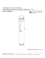
Epson ELPMBC01 Installation Guide - Page 4
Installation to Ceiling Plate, fig. 1.1, fig. 1.2, DETAIL 1 - elpmbp01
 |
UPC - 010343868649
View all Epson ELPMBC01 manuals
Add to My Manuals
Save this manual to your list of manuals |
Page 4 highlights
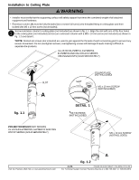
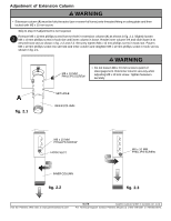
Installation to Ceiling Plate WARNING • Installer must verify that the supporting surface will safely support four times the combined weight of all attached equipment and hardware. • Extension column (A) must be fully threaded (six or seven full turns) onto threaded fitting in ceiling plate and then locked with M5 x 10 mm screw (not included). Screw extension column to ceiling plate (not included) as shown in fig. 1.1. Align the slot with one of the four holes 1 in the ceiling plate (not included) and secure extension column with a M5 x 10 mm screw (not included) as shown in fig. 1.2 and detail 1. *NOTE: Slotted set screws (not included) are used to jam against the threads of each connecting joint to prevent any excess movement. Do not overtighten screws; overtightening screws will damage threads making it difficult to separate the products. UL LISTED ELPMBP01, ELPMBP02, ELPMBP03 AND CMJ OR ACC SERIES CEILING MOUNTS (SOLD SEPARATELY) SLOT A fig. 1.1 PROJECTOR MOUNT (NOT SHOWN) UL LISTED ELPMBPRG, ELPMBPJF AND PRG OR PJF SERIES (SOLD SEPARATELY) SLOT CEILING PLATE (NOT INCLUDED) M5 x 10 mm SCREW (NOT INCLUDED) DETAIL 1 *SET SCREWS (NOT INCLUDED) M5 x 10 mm SCREW (NOT INCLUDED) Visit the Peerless Web Site at www.peerlessmounts.com A fig. 1.2 4 of 6 ISSUED: 03-06-08 SHEET #: 154-9009-2 07-10-08 For Technical Support Contact Peerless Mounts at 1-800-729-0307 or 708-865-8870.
-
 1
1 -
 2
2 -
 3
3 -
 4
4 -
 5
5 -
 6
6
 |
 |
