Epson H6000II User Manual - Page 2
Part Names, DIP Switch Tables - tm printer
 |
View all Epson H6000II manuals
Add to My Manuals
Save this manual to your list of manuals |
Page 2 highlights
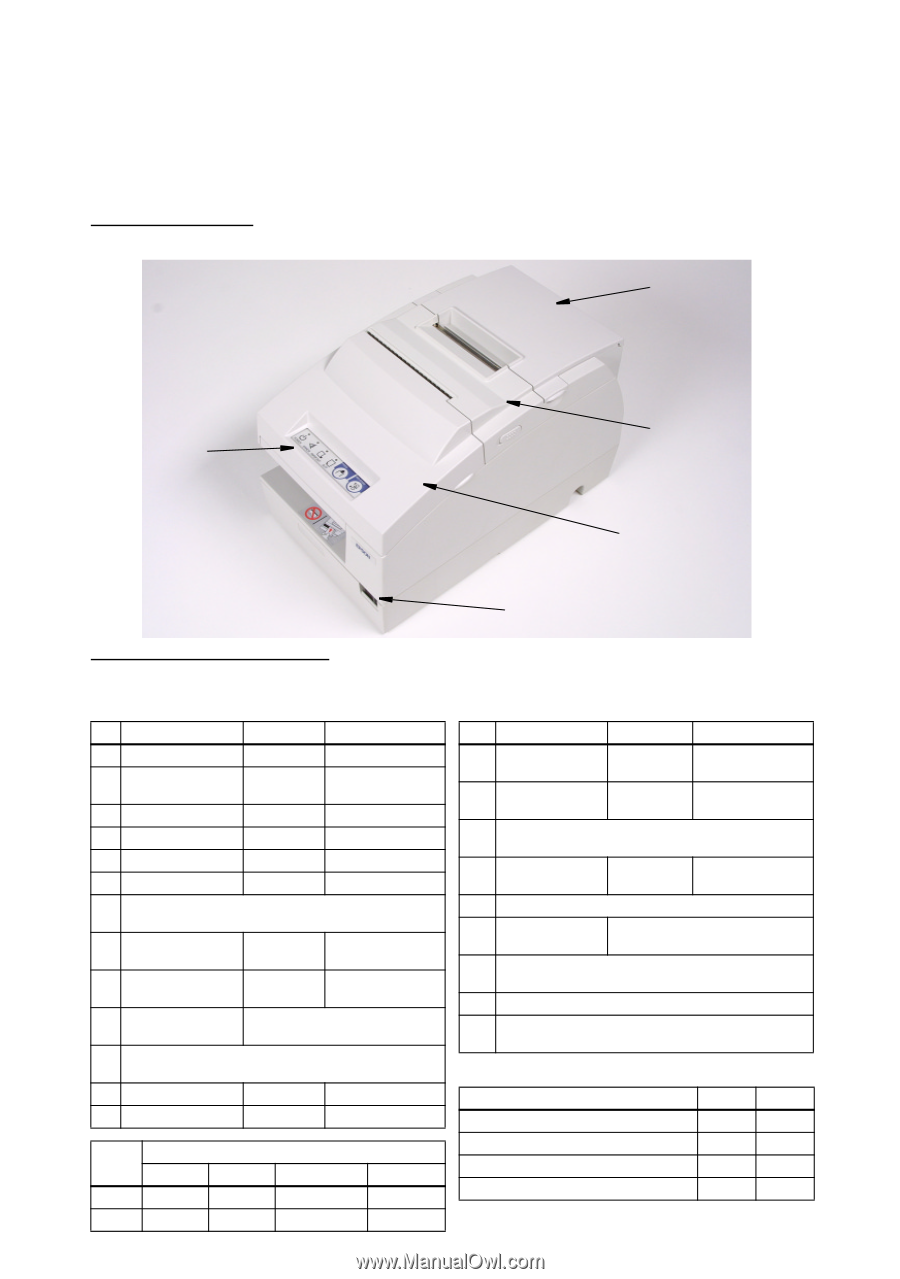
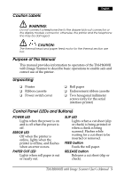
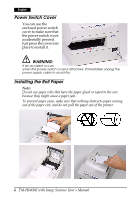
This TM-H6000II with Image Scanner printer combines slip, impact, and two-color thermal printing with the new image scanner function. The image scanner can digitize a check image, which offers you an efficient method of check processing. Part Names 1 roll paper cover 5 control panel 2 unit cover 3 front cover 4 power switch DIP Switch Tables Serial SW Function ON OFF 1-1 Data receive error Ignored Prints "?" 1-2 Receive buffer capacity 45 bytes 4 KB 1-3 Handshaking XON/XOFF DTR/DSR 1-4 Data word length 7 bits 8 bits 1-5 Parity check Enabled Disabled 1-6 Parity selection Even Odd 1-7 Transmission speed (See table below.) 1-8 2-1 Handshaking Receive Offline or Receive (BUSY condition) buffer full buffer full 2-2 Customer display Connected Not connected connection 2-3 Print density 2-4 See Table A. 2-5 Internal use. Fixed to Off. 2-6 2-7 I/F pin 6 reset Enabled Disabled 2-8 I/F pin 25 reset Enabled Disabled SW Transmission speed (bps)-bits per second 4800 9600 192000 38400 1-7 ON OFF ON OFF 1-8 ON ON OFF OFF Parallel SW Function ON OFF 1-1 Auto line feed Always enabled Always disabled 1-2 Receive buffer 45 bytes capacity 4 KB 1-3~ Reserved. Fixed to Off. 1-8 2-1 Handshaking Receive (BUSY condition) buffer full Offline or Receive buffer full 2-2 Internal use. Do not change setting. Fixed to Off. 2-3 Print density 2-4 See Table A. 2-5 Internal use. Fixed to Off. 2-6 2-7 Reserved (for serial interface) Fixed to Off. 2-8 I/F pin 31 reset signal. Do not change setting. Fixed to On. Table A Print density/low power 1 Print density (Light) 2 3 4 Print density (Dark) SW 2-3 ON OFF ON OFF SW 2-4 ON OFF OFF ON
-
 1
1 -
 2
2 -
 3
3 -
 4
4 -
 5
5 -
 6
6 -
 7
7 -
 8
8 -
9
-
10
-
11
-
12
-
13
-
14
 |
 |