Fender Jazzmaster Ultralight Owner Manual - Page 7
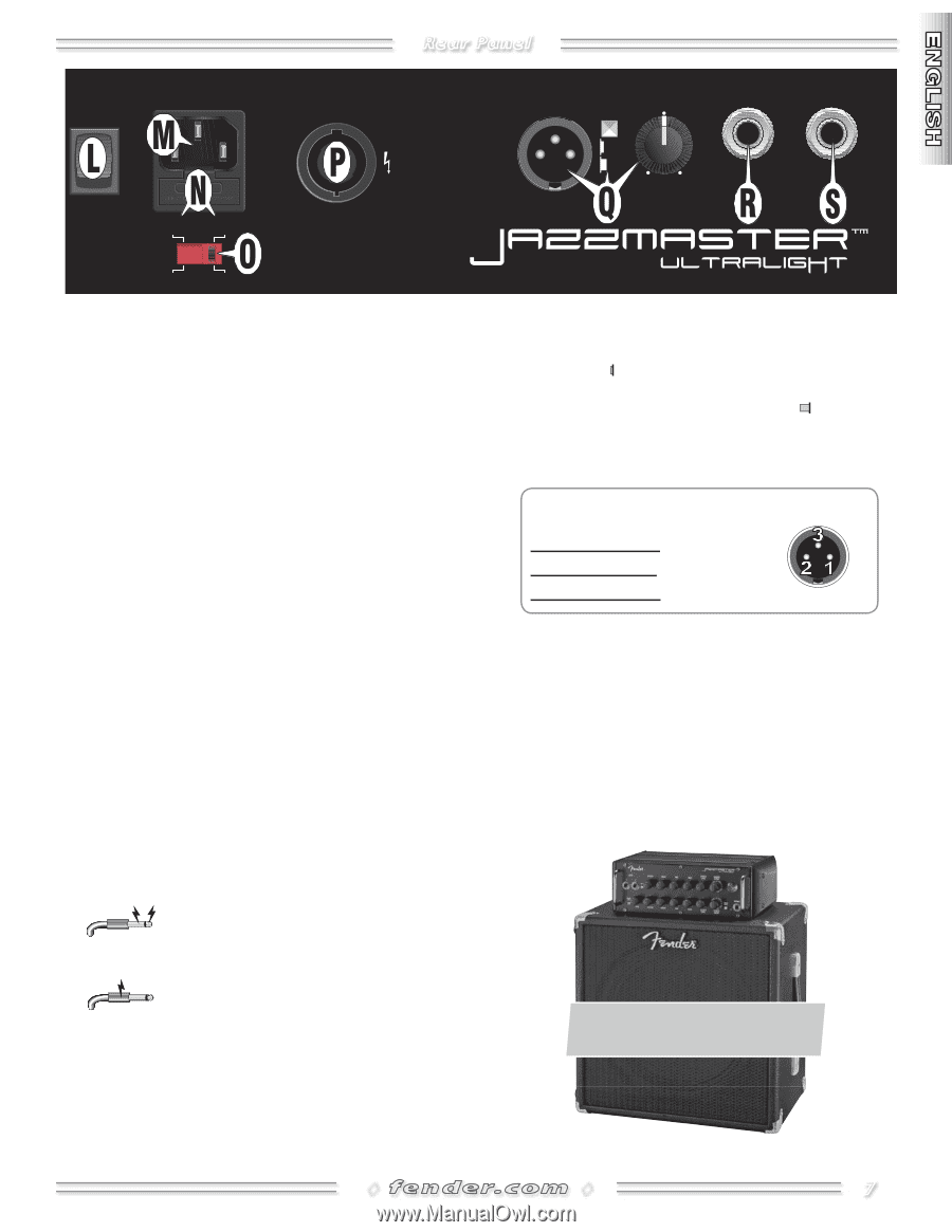
Power, M. Iec Power Input Socket, N. Fuse, O. Voltage Selector, Speaker Output, Q. Line Output, - amplifier
 |
View all Fender Jazzmaster Ultralight manuals
Add to My Manuals
Save this manual to your list of manuals |
Page 7 highlights
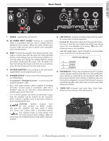
�� INPUT POWER 500W FUSE ��� ���� ���� ���� Rear Panel ��� 12 0 ���� L. POWER-Switches the unit ON-OFF. M. IEC POWER INPUT SOCKET-Connect to a grounded outlet in accordance with the correct Voltage Selector setting for your location. When you travel outside your country, make sure you have a power cord compatible with each destination. N. FUSE-Protects the amplifier from electrical faults. Only replace a blown fuse with the type and rating specified for the correct Voltage Selector {O} setting. Install the correct fuse when you change the Voltage Selector setting and before connecting the power cord. To replace the fuse, first remove the power cord, then use a screwdriver to pry the fuse holder out from the input socket. O. VOLTAGE SELECTOR-Set according to the local power supply before connecting the power cord. P. SPEAKER OUTPUT-Connect one of the following speaker configurations: • A Jazzmaster™ Ultralight Enclosure-connect using the supplied Speakon® cable. • Any 2-ohm guitar speaker cabinet capable of handling 250-watts-connect using a 2-conductor cable with a Speakon® plug on one end and a plug matching the speaker input on the other end. • A 4- or 8-ohm speaker will work, but the power output from the amplifier will be reduced by the mismatch. Never connect a speaker load of less than 2-ohms to avoid overloading the unit. CAUTION: Speaker outputs have 20 volts present on BOTH conductors and the amplifier will shut down if either one comes into contact with a grounded surface. Any exposed metal on plug jackets must not touch ground when speaker cables are connected; use insulated (plastic) plug jackets whenever possible. Q. LINE OUTPUT-Speaker emulated, balanced XLR output for connection to sound equipment. • Ground Lift press IN to disconnect the ground connection (pin 1) from the Line Output jack which may reduce noise from non-standard local wiring. Leave OUT whenever noise is not a problem. • Line Out Level adjusts signal strength to accommodate input sensitivities of external equipment. XLR Pin Out (Wiring) 1 Ground 2 Positive 3 Negative R. FOOTSWITCH-Plug in the included footswitch to enable remote channel selection and effects on-off switching for each channel as indicated by the footswitch LEDs. The front panel Channel Select button is disabled when the footswitch is plugged in. Connect the footswitch using an unshielded speaker cable rather than an instrument cable whenever possible. S. TUNER OUT-Connect your tuner here. Press Tuner/ Mute {I} on the front panel for silent tuning. Recommended Enclosure: The Fender® Jazzmaster™ Ultralight Enclosure (Part Number: 227-7700-000) ◊ ◊ 7
-
 1
1 -
 2
2 -
 3
3 -
 4
4 -
 5
5 -
 6
6 -
 7
7 -
 8
8 -
 9
9 -
 10
10
 |
 |