Fisher and Paykel OB30DDPTDX2 Installation Guide / Guide d installation - Page 9
Electrical Connection To Junction Box, Secure The Oven To The Cabinetry
 |
View all Fisher and Paykel OB30DDPTDX2 manuals
Add to My Manuals
Save this manual to your list of manuals |
Page 9 highlights
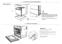
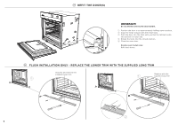
8 ELECTRICAL CONNECTION TO JUNCTION BOX Junction box location for: undercounter installation Junction box location for: wall installation OB30 Single Voltage Max. current Max. draw load 208V 16.6 A 3.5 kW 240V 19.4 A 4.6 kW OB30 Double Voltage Max. current Max. draw load 208V 33.2 A 7.0 kW 240V 38.3 A 9.2 kW Nameplate 1 Disconnect the power supply. 2 Remove the junction box cover. 3 Connect the oven cable to the junction box through the U.L.-listed conduit connector. 4 Connect the two black wires together with twist-on connectors. 5 Connect the two red wires together with twist-on connectors. 6 Connect electrical connection according to local codes and ordinances. If local codes permit connecting the cabinet-grounding conductor to the neutral white wire in the junction box: 7AConnect the factory-taped green and white oven cable wires to the neutral (white) wire in the junction box. 8AReplace the junction box cover. red wires cable from power supply red wires box cable from power supply box white and green grounding oven wires - factory taped black wires green grounding UL - listed oven wires conduit connector - factory taped white wires black wires UL - listed conduit connector OR If local codes DO NOT PERMIT connecting the cabinet-grounding conductor to the neutral (white) wire in junction box: 7BSeparate the factory-taped green and white oven cable wires. 8BConnect the white oven cable wire to the neutral (white) wire in junction box. 9BConnect the green grounding oven cable wire to a grounded wire in the junction box. !0BReplace the junction box cover. OR If connecting to a four-wire electrical system: 7CSeparate the green and white oven cable wires. 8CConnect the white oven cable wire to the neutral (white) wire in junction box. 9CConnect the green grounding oven cable wire to the (green) grounding wire in the junction box. Do not connect the green grounding wire to the neutral (white) wire in junction box. !0CReplace the junction box cover. 9 SECURE THE OVEN TO THE CABINETRY 1 Position the oven in the prepared cavity. IMPORTANT! Do not lift the oven by the door handle. 2 Use the supplied screws and spacers to secure the oven to the cabinetry. Double oven models only: There are 4 screws and spacers provided (two per side). IMPORTANT! ● Do not over-tighten the screws. ● Take care not to damage the lower trim of the oven. ● Do not seal the oven into the cabinetry with silicone or glue. This makes future servicing difficult. Fisher & Paykel will not cover the costs of removing the oven, or of damage caused by this removal. Ensure supplied spacer is fitted between oven and cabinetry 8
-
 1
1 -
2
-
3
-
 4
4 -
 5
5 -
 6
6 -
 7
7 -
 8
8 -
 9
9 -
 10
10 -
 11
11 -
 12
12 -
 13
13 -
 14
14 -
15
-
16
-
17
-
18
-
19
-
20
-
21
-
22
-
23
-
24
 |
 |
