Fluke 271-U 115V Product Manual - Page 26
Front Panel Connections, Rear Panel Connections
 |
View all Fluke 271-U 115V manuals
Add to My Manuals
Save this manual to your list of manuals |
Page 26 highlights
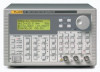
271 Users Manual Front Panel Connections MAIN OUT MAIN OUT is the 50 Ω / 600 Ω output from the main generator. It will provide up to 20 V p-p into a high-impedance load or 10 V p-p into a matched 50 Ω / 600 Ω load. It can tolerate a short circuit for 60 seconds. Caution To avoid risk of damage to the instrument, do not apply external voltages to this output. AUX OUT AUX OUT is a TTL/CMOS level output synchronous with MAIN OUT. Symmetry is the same as that set for the main output but the phase relationship between MAIN OUT and AUX OUT is determined by the PHASE setting specified on the TRIGger menu. AUX OUT logic levels are nominally 0 V and 5 V from typically 50 Ω. AUX OUT will withstand a short-circuit. Caution To avoid risk of damage to the instrument, do not apply external voltages to this output. EXT TRIG EXT TRIG is the external trigger input for trigger, gate, sweep, FSK and hop operating modes. It is also the input used to synchronize the generator as a slave to an external master generator. Caution To avoid risk of damage to the instrument, do not apply external voltages exceeding ±10 V to this input. Rear Panel Connections CLOCK IN/OUT The function of the CLOCK IN/OUT socket is set from the SYStem menu as follows: INPUT The socket becomes an input for an external clock. OUTPUT This is the default setting. The internal clock is made available at the socket. When two or more generators are synchronized the master is set to OUTPUT and the signal is used to drive the CLOCK IN inputs of the slaves. PHASE LOCK When two or more generators are synchronized the slaves are set to PHASE LOCK. As an output the logic levels are nominally 1 V and 4 V from typically 50 Ω. CLOCK IN/OUT will withstand a short-circuit. When used as an input the threshold is TTL/CMOS compatible. 3-2 MyFlukeStore Shop for Fluke products online at: www. .com 1.888.610.7664
-
 1
1 -
2
-
3
-
4
-
5
-
6
-
7
-
8
-
9
-
10
-
11
-
12
-
13
-
14
-
15
-
16
-
17
-
18
-
19
-
20
-
 21
21 -
 22
22 -
 23
23 -
 24
24 -
 25
25 -
 26
26 -
 27
27 -
 28
28 -
 29
29 -
 30
30 -
 31
31 -
32
-
33
-
34
-
35
-
36
-
37
-
38
-
39
-
40
-
41
-
42
-
43
-
44
-
45
-
46
-
47
-
48
-
49
-
50
-
51
-
52
-
53
-
54
-
55
-
56
-
57
-
58
-
59
-
60
-
61
-
62
-
63
-
64
-
65
-
66
-
67
-
68
-
69
-
70
-
71
-
72
-
73
-
74
-
75
-
76
-
77
-
78
-
79
-
80
-
81
-
82
-
83
-
84
-
85
-
86
-
87
-
88
-
89
-
90
-
91
-
92
-
93
-
94
-
95
-
96
-
97
-
98
-
99
-
100
-
101
-
102
-
103
-
104
-
105
-
106
-
107
-
108
-
109
-
110
-
111
-
112
-
113
-
114
-
115
-
116
-
117
-
118
-
119
-
120
-
121
-
122
-
123
-
124
-
125
-
126
-
127
-
128
-
129
-
130
-
131
-
132
 |
 |
