Fluke 9040 User Manual
Fluke 9040 Manual
 |
View all Fluke 9040 manuals
Add to My Manuals
Save this manual to your list of manuals |
Fluke 9040 manual content summary:
- Fluke 9040 | User Manual - Page 1
9040 Phase Rotation Indicator Users Manual PN 2438546 April 2005, Rev.2, 5/11 © 2005-2011 Fluke Corporation. All rights reserved. Specifications are subject to change without notice. All product names are trademarks of their respective companies. - Fluke 9040 | User Manual - Page 2
to extend any other warranty on Fluke's behalf. To obtain service during the warranty period, contact your nearest Fluke authorized service center to obtain return authorization information, then send the product to that Service Center with a description of the problem. THIS WARRANTY IS YOUR ONLY - Fluke 9040 | User Manual - Page 3
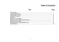
Table of Contents Title Page Introduction...1 Contacting Fluke 1 Unpacking the 9040 2 Safety Information 3 Symbols...5 Elements of the 9040 6 Determine the Rotary Field Direction 7 Maintaining the 9040 8 Replacing the Fuse (9040UK only 9 Specifications ...10 i - Fluke 9040 | User Manual - Page 4
ii - Fluke 9040 | User Manual - Page 5
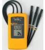
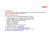
The Fluke 9040 Phase Rotation Indicator (the 9040) is a handheld instrument designed to detect the rotary field of three-phase systems. How to Contact Fluke To contact Fluke, call one of the following telephone numbers: • Technical Support USA: 1-800-44-FLUKE (1-800-443-5853) • Calibration/Repair - Fluke 9040 | User Manual - Page 6
9040 Users Manual Unpacking the 9040 The 9040 is available in three configurations. Depending on your purchase, the 9040 ships with these items: • 9040 o 3 self-retaining test probes, 1000 V CAT II o 3 alligator clips, 1000 V CAT III/600 V CAT IV o Users Manual • 9040UK o 3 fused test probes, 1000 V - Fluke 9040 | User Manual - Page 7
Phase Rotation Indicator Safety Information Safety Information Caution identifies conditions and actions that may damage the 9040. Warning identifies conditions and actions that pose hazard(s) to the user. XW Warning To prevent possible electrical shock, fire, or personal injury: • Carefully read - Fluke 9040 | User Manual - Page 8
9040 Users Manual • Measurements can be adversely affected by impedances of additional operating circuits connected in parallel or by transient currents. • Verify operation prior to measuring hazardous voltages (voltages above 30 V ac rms, 42 V ac peak and 60 V dc). • Do not use the 9040 with any of - Fluke 9040 | User Manual - Page 9
Phase Rotation Indicator Symbols Symbols The following symbols appear on the 9040 or in this manual. Table 1. Symbols W Risk of Danger. Important information. See manual. J Earth ground. the primary supply level, such as an electricity meter or an overhead or underground utility service. 5 - Fluke 9040 | User Manual - Page 10
9040 Users Manual Elements of the 9040 Indicators, buttons, and jacks are shown in Figure 1. Test lead input jack L1, L2, L3 Indicators Clockwise Rotation LCD Indicator Counter-Clockwise Rotation LCD Indicator Brief Instructions on instrument rear Figure 1. The 9040 Phase Rotation Indicator - Fluke 9040 | User Manual - Page 11
Phase Rotation Indicator Determine the Rotary Field Direction Determine the Rotary Field Direction To determine the rotary field direction: 1. Connect the test probes to the end of the test leads. 2. Connect the test probes to the three mains phases. 3. The green ON indicator shows that the - Fluke 9040 | User Manual - Page 12
9040 Users Manual Maintaining the 9040 W Caution To prevent damage to the 9040: • Do not attempt to repair or service the 9040 unless qualified to do so. • Make sure that the relevant calibration, performance test, and service information is being used. • Do not use abrasives or solvents. Abrasives - Fluke 9040 | User Manual - Page 13
Phase Rotation Indicator Replacing the Fuse (9040UK only) Replacing the Fuse (9040UK only) XW Warning For safe operation and maintenance of the product: • Use only specified replacement fuses. See Specifications section. • Before you replace the fuse, disconnect the accessory (cable or probe) at - Fluke 9040 | User Manual - Page 14
9040 Users Manual Specifications Environmental Operating Temperature 0 °C to +40 °C Pollution Degree 2 Type of Protection IP 40 Mechanical Specifications Size 124 x 61 x 27 mm (4.9 x 2.4 x 1.1 to 690 V ac Frequency Range (fn) 15 to 400 Hz Current Pickup 1 mA Nominal Test Current (in per phase) 1 mA
-
 1
1 -
 2
2 -
 3
3 -
 4
4 -
 5
5 -
 6
6 -
 7
7 -
8
-
9
-
10
-
11
-
12
-
13
-
14
 |
 |

PN 2438546
April 2005, Rev.2, 5/11
© 2005-2011 Fluke Corporation. All rights reserved. Specifications are subject to change without notice.
All product names are trademarks of their respective companies.
9040
Phase Rotation Indicator
Users Manual