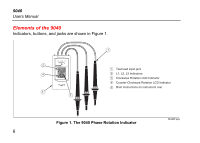
Fluke 9040 User Manual - Page 11
Determine the Rotary Field Direction - leads
 |
View all Fluke 9040 manuals
Add to My Manuals
Save this manual to your list of manuals |
Page 11 highlights
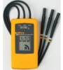
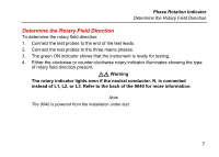
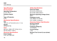
Phase Rotation Indicator Determine the Rotary Field Direction Determine the Rotary Field Direction To determine the rotary field direction: 1. Connect the test probes to the end of the test leads. 2. Connect the test probes to the three mains phases. 3. The green ON indicator shows that the instrument is ready for testing. 4. Either the clockwise or counter-clockwise rotary indicator illuminates showing the type of rotary field direction present. XW Warning The rotary indicator lights even if the neutral conductor, N, is connected instead of L1, L2, or L3. Refer to the back of the 9040 for more information. Note The 9040 is powered from the installation under test. 7
-
 1
1 -
2
-
3
-
4
-
5
-
 6
6 -
 7
7 -
 8
8 -
 9
9 -
 10
10 -
 11
11 -
 12
12 -
 13
13 -
 14
14
 |
 |
Phase Rotation Indicator
Determine the Rotary Field Direction
7
Determine the Rotary Field Direction
To determine the rotary field direction:
1.
Connect the test probes to the end of the test leads.
2.
Connect the test probes to the three mains phases.
3.
The green ON indicator shows that the instrument is ready for testing.
4.
Either the clockwise or counter-clockwise rotary indicator illuminates showing the type
of rotary field direction present.
XW
Warning
The rotary indicator lights even if the neutral conductor, N, is connected
instead of L1, L2, or L3. Refer to the back of the 9040 for more information.
Note
The 9040 is powered from the installation under test.