Foxconn A79A-S English Manual. - Page 38
Advanced Chipset Features
 |
View all Foxconn A79A-S manuals
Add to My Manuals
Save this manual to your list of manuals |
Page 38 highlights
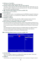
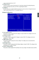
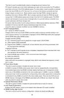
Advanced Chipset Features CMOS Setup Utility - Copyright (C) 1985-2005, American Megatrends, Inc. Advanced Chipset Features NorthBridge Chipset Configuration Help Item ► Memory Configuration [Press Enter] ► DRAM Timing Configuration [Press Enter] Current CAS Latency(CL) 5 CLK, N/A Current RAS/CAS Delay(TRCD) 5 CLK, N/A Current TRP 5 CLK, N/A Current TRAS 15 CLK, N/A Current TRRD 7 CLK, N/A Current TRC 30 CLK, N/A PCI Express Configuration GFX Dual Slot Configuration GFX2 Dual Slot Configuration Peer-to-Peer among GFX/GFX2 GPP Slots Power Limit, W [Auto] [Auto] [Disabled] [25] ► PCIE 16X Port 1 [Press Enter] Move Enter:Select +/-/:Value F10:Save ESC:Exit F1:General Help F9:Optimized Defaults ► Memory Configuration/DRAM Timing Configuration Press to go to the submenu. 3 The following six items display the values configured at the settings of "DRAM Timing Configuration". ► Current CAS Latency(CL) This item shows the CAS latency. The CAS Latency is the number of clock cycles that elapse from the time the request for data is sent to the actual memory location until the data is transmitted from the module. ► Current RAS/CAS Delay(TRCD) This item displays a delay time (in clock cycles) between the CAS and RAS strobe signals. ► Current TRP This item displays the row precharge time (in clock cycles) . ► Current TRAS This item displays the minimum RAS# active time (in clock cycles) . ► Current TRRD This item displays a delay time (in clock cycles) between the RAS and RAS strobe signals. ► Current TRC This item displays the row cycle time (in clock cycles) . ► GFX Dual Slot Configuration Before configure the CrossFireTM technology, you need enable two PCI Express slots in BIOS first. This item is used to configure PCI_E1_x16 slot and PCI_E2_x16 slot for the ATI CrossFireTM technology. Select [Auto], BIOS will automatically detect whether PCI_E1/E2_x16 Slots are available or not; Select [Enabled], you can configure the CrossFireTM Technology based on PCI_E1_x16 slot and PCI_E2_x16 slot; Select [Disabled], the two slots can not be used for the CrossFireTM Technology. ► GFX2 Dual Slot Configuration This item is used to configure PCI_E3_x16 slot and PCI_E4_x16 slot for the advanced CrossFireTM technology. Select [Auto], BIOS will automatically detect whether PCI Express Slots are available or not; Select [Enabled], you can configure the CrossFireTM Technology based on 31
-
 1
1 -
2
-
3
-
4
-
5
-
6
-
7
-
8
-
9
-
10
-
11
-
12
-
13
-
14
-
15
-
16
-
17
-
18
-
19
-
20
-
21
-
22
-
23
-
24
-
25
-
26
-
27
-
28
-
29
-
30
-
31
-
32
-
 33
33 -
 34
34 -
 35
35 -
 36
36 -
 37
37 -
 38
38 -
 39
39 -
 40
40 -
 41
41 -
 42
42 -
 43
43 -
44
-
45
-
46
-
47
-
48
-
49
-
50
-
51
-
52
-
53
-
54
-
55
-
56
-
57
-
58
-
59
-
60
-
61
-
62
-
63
-
64
-
65
-
66
-
67
-
68
-
69
-
70
-
71
-
72
-
73
-
74
-
75
-
76
-
77
-
78
-
79
-
80
-
81
-
82
-
83
-
84
-
85
-
86
-
87
-
88
-
89
-
90
-
91
-
92
-
93
-
94
-
95
-
96
-
97
-
98
-
99
-
100
-
101
-
102
-
103
-
104
-
105
-
106
-
107
-
108
-
109
-
110
-
111
-
112
-
113
-
114
-
115
 |
 |
