Foxconn A7GMP-S English Manual. - Page 38
► SIDEPORT Clock Speed, ► UMA-SP Interleave Mode, ► Primary Video Controller, ► DCT Unganged Mode
 |
View all Foxconn A7GMP-S manuals
Add to My Manuals
Save this manual to your list of manuals |
Page 38 highlights
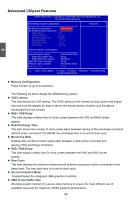
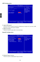
3 This is a memory allocation method addition to the Unified Memory Architecture (UMA) concept, wherein a static amount of page-locked graphics memory is allocated during driver initialization. This fixed amount of memory will provide the user with a guaranteed graphics memory at all times, and will no longer be available to the OS. ► SIDEPORT Clock Speed This item will appear only when "Internal Graphics Mode" is set to [UMA+SIDEPORT], it used to adjust sideport clock speed. ► UMA-SP Interleave Mode This item will appear only when "Internal Graphics Mode" is set to [UMA+SIDEPORT], it used to set the UMA and sideport interleave mode. Setting values are: [Auto], [Coarse], [Fine]. The interleave Ratio/Size selected based on system configuration. ► Primary Video Controller This item allows you to select the priority of boot sequence from different display devices. Setting values are: [GFX0-IGFX-PCI], [PCI-GFX0-IGFX], [IGFX-GFX0-PCI]. (GFX0-PCI Express x16 graphics card; IGFX-onboard VGA; PCI-PCI graphics card.) Memory Configuration CMOS Setup Utility - Copyright (C) 1985-2006, American Megatrends, Inc. Memory Configuration Memory Configuration Help Item DCT Unganged Mode [Always] This allows selection of unganged DRAM mode (64-bit width) . Auto = Ganged mode Always = Unganged mode Move Enter:Select +/-/:Value F10:Save ESC:Exit F1:General Help F9:Optimized Defaults ► DCT Unganged Mode DCT stands for DRAM Controller. Ganged refers to the use of both DRAM controllers within a memory controller acting in concert to access memory. For a description of ganged (128-bit DRAM data width) and unganged (64-bit DRAM data width) DRAM modes : Ganged channels (DDR2) : ■ DCT channels A and B can be ganged as a single logical 128-bit DIMM. ■ Offers highest DDR2 bandwidth. ■ Requires both DIMMs in a logical pair to have identical size and timing parameters, both DCTs programmed identically. 31
-
 1
1 -
2
-
3
-
4
-
5
-
6
-
7
-
8
-
9
-
10
-
11
-
12
-
13
-
14
-
15
-
16
-
17
-
18
-
19
-
20
-
21
-
22
-
23
-
24
-
25
-
26
-
27
-
28
-
29
-
30
-
31
-
32
-
 33
33 -
 34
34 -
 35
35 -
 36
36 -
 37
37 -
 38
38 -
 39
39 -
 40
40 -
 41
41 -
 42
42 -
 43
43 -
44
-
45
-
46
-
47
-
48
-
49
-
50
-
51
-
52
-
53
-
54
-
55
-
56
-
57
-
58
-
59
-
60
-
61
-
62
-
63
-
64
-
65
-
66
-
67
-
68
-
69
-
70
-
71
-
72
-
73
-
74
-
75
-
76
-
77
-
78
-
79
-
80
-
81
-
82
-
83
-
84
-
85
-
86
-
87
-
88
-
89
-
90
-
91
-
92
-
93
-
94
-
95
-
96
-
97
-
98
-
99
-
100
-
101
-
102
-
103
-
104
-
105
 |
 |
