Foxconn H61M-S User manual - Page 11
Layout, PCH_ME_ENABLE Jumper
 |
View all Foxconn H61M-S manuals
Add to My Manuals
Save this manual to your list of manuals |
Page 11 highlights
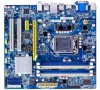
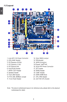
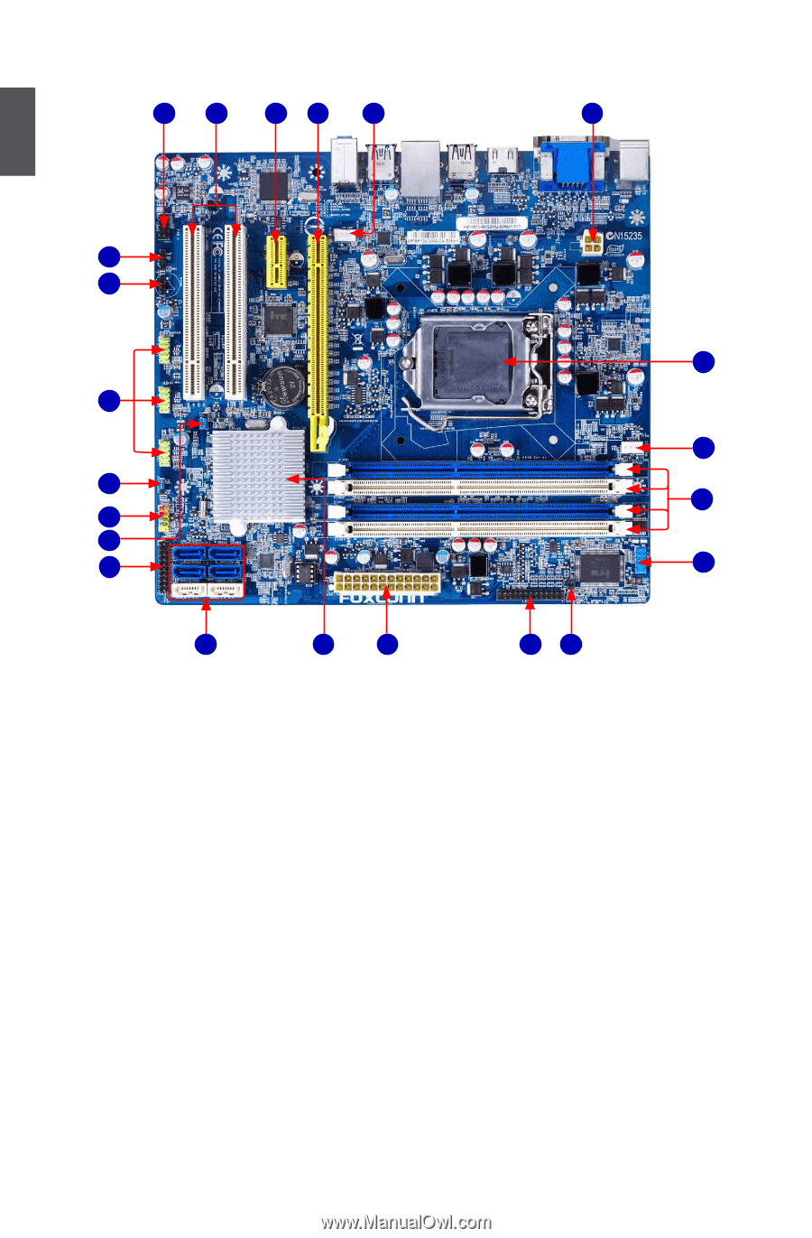
1-2 Layout 6 5 4 3 2 1 1 7 8 22 9 21 10 20 11 12 13 19 14 15 16 17 18 1. 4-pin ATX 12V Power Connector 2. SYS_FAN1 Header 3. PCI Express x16 Slot 4. PCI Express x1 Slot 5. PCI Express Slot 6. Front Audio Header 7. SPDIF_OUT Header 8. Speaker Header 9. Front USB Header 10. PCH_ME_ENABLE Jumper 11. Front Panel Header 12. Clear CMOS Jumper 13. TPM Header 14. SATA Connectors 15 Chipset: Intel® H61 16. 24-pin ATX Power Connector 17. LPT Header 18. INTR2 Header 19. COM1 Header 20. DDR3 DIMM Slots 21. CPU_FAN Header 22. LGA1155 CPU Socket Note : The above motherboard layout is for reference only, please refer to the physical motherboard for detail. 4
-
 1
1 -
2
-
3
-
4
-
5
-
 6
6 -
 7
7 -
 8
8 -
 9
9 -
 10
10 -
 11
11 -
 12
12 -
 13
13 -
 14
14 -
 15
15 -
 16
16 -
17
-
18
-
19
-
20
-
21
-
22
-
23
-
24
-
25
-
26
-
27
-
28
-
29
-
30
-
31
-
32
-
33
-
34
-
35
-
36
-
37
-
38
-
39
-
40
-
41
-
42
-
43
-
44
-
45
-
46
-
47
-
48
-
49
-
50
-
51
-
52
-
53
-
54
-
55
-
56
-
57
-
58
-
59
-
60
-
61
-
62
-
63
-
64
-
65
-
66
-
67
-
68
-
69
-
70
-
71
-
72
-
73
 |
 |
1
4
1-2 Layout
Note : The above motherboard layout is for reference only, please refer to the physical
motherboard for detail.
1. 4-pin ATX 12V Power Connector
2. SYS_FAN1 Header
3. PCI Express x16 Slot
4. PCI Express x1 Slot
5. PCI Express Slot
6. Front Audio Header
7. SPDIF_OUT Header
8. Speaker Header
9. Front USB Header
10. PCH_ME_ENABLE Jumper
11. Front Panel Header
12.
Clear CMOS Jumper
13. TPM Header
14.
SATA Connectors
15
Chipset: Intel
®
H61
16. 24-pin ATX Power Connector
17. LPT Header
18. INTR2 Header
19. COM1 Header
20.
DDR3 DIMM Slots
21. CPU_FAN Header
22. LGA1155 CPU Socket
1
7
2
6
8
13
17
19
22
20
12
18
9
21
10
11
14
16
15
5
3
4