Foxconn H61MXP User manual - Page 23
Fan Connectors: CPU_FAN, SYS_FAN1, Chassis Intrusion Alarm Header : INTR - bios
 |
View all Foxconn H61MXP manuals
Add to My Manuals
Save this manual to your list of manuals |
Page 23 highlights
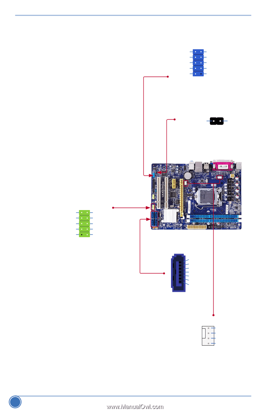
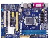
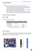
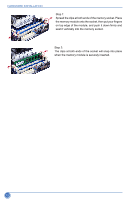
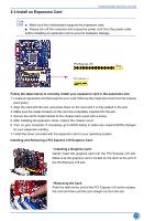
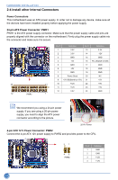
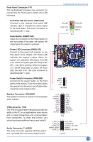
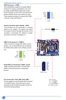
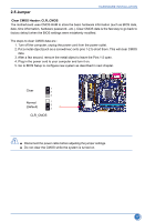
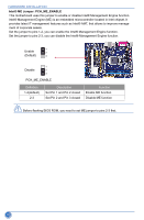
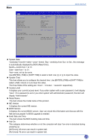
HARDWARE INSTALLATION COM Connector : COM2 This motherboard supports one serial RS232 COM port for legacy compatibility. User must purchase another RS232 cable with a 9-pin D-sub connector at one end to connect with the external RS232 device and another end with 10-pin female connector to connect with COM1 connector in the motherboard. Chassis Intrusion Alarm Header : INTR The connector can be connected to a security switch on the chassis. The system can detect the chassis intrusion through the function of this connector. If eventually the chassis is closed, the system will send a message out. USB 2.0 Connectors: F_USB1/2 These connectors comply with USB 2.0 speci- fication, you can get USB ports by connecting the USB module cable to any of these connec- tors. VCC DD+ GND EMPTY 12 9 10 VCC DD+ GND GND F_USB1/2 Serial ATA 2.0 Connectors: SATA_1/2/3/4 These connectors are used to connect with SATA 2.0 Hard Disk drives or optical disc devices. Fan Connectors: CPU_FAN, SYS_FAN1 The fan speed can be controlled and monitored in the BIOS Setup. These fans can be automatically turned off after the system enters S3, S4 and S5 sleeping states. DCD SOUT GND RTS RI 12 9 10 SIN DTR DSR CTS EMPTY COM2 INTRUDERJ 1 GND INTR 1 GND TX+ TXGND RXRX+ GND SATA_1/2/3/4 1 GND POWER SENSE CONTROL CPU_FAN/SYS_FAN1 16
-
 1
1 -
2
-
3
-
4
-
5
-
6
-
7
-
8
-
9
-
10
-
11
-
12
-
13
-
14
-
15
-
16
-
17
-
 18
18 -
 19
19 -
 20
20 -
 21
21 -
 22
22 -
 23
23 -
 24
24 -
 25
25 -
 26
26 -
 27
27 -
 28
28 -
29
-
30
-
31
-
32
-
33
-
34
-
35
-
36
-
37
-
38
-
39
-
40
-
41
-
42
-
43
-
44
-
45
-
46
-
47
-
48
-
49
-
50
-
51
-
52
-
53
-
54
-
55
-
56
-
57
-
58
-
59
-
60
-
61
-
62
-
63
-
64
-
65
-
66
-
67
-
68
-
69
-
70
 |
 |