Foxconn H61MXP User manual - Page 34
Internal READ Command to PRECHARGE Command delay
 |
View all Foxconn H61MXP manuals
Add to My Manuals
Save this manual to your list of manuals |
Page 34 highlights
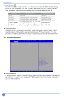
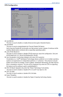
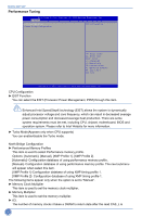
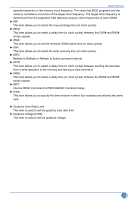
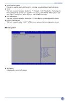
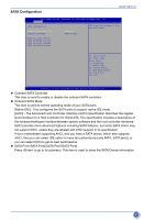
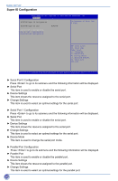
BIOS SETUP asserted depends on the memory clock frequency. The value that BIOS programs into the memory controller is a function of the target clock frequency. The target clock frequency is determined from the supported CAS latencies at given clock frequencies of each DIMM. ► tRP This item allows you to select the row precharge time (in clock cycles). ► tRCD This item allows you to select a delay time (in clock cycles) between the CAS# and RAS# strobe signals. ► tRAS This item allows you to set the minimum RAS# active time (in clock cycles). ► tWR This item allows you to select the write recovery time (in clock cycles). ► tRFC Refresh to Refresh or Refresh to Active command interval. ► tWTR This item allows you to select a delay time (in clock cycles) between sending the last data from a write operation to the memory and issuing a read command. ► tRRD This item allows you to select a delay time (in clock cycles) between the RAS# and RAS# strobe signals. ► tRTP Internal READ Command to PRECHARGE Command delay ► tFAW This item allows you to specify the time window in which four activates are allowed the same rank. ► Graphics Core Ratio Limit This item is used to set the graphics care ratio limit. ► Graphics Voltage(1/256) This item is used to set the graphics voltage. 27
-
 1
1 -
2
-
3
-
4
-
5
-
6
-
7
-
8
-
9
-
10
-
11
-
12
-
13
-
14
-
15
-
16
-
17
-
18
-
19
-
20
-
21
-
22
-
23
-
24
-
25
-
26
-
27
-
28
-
 29
29 -
 30
30 -
 31
31 -
 32
32 -
 33
33 -
 34
34 -
 35
35 -
 36
36 -
 37
37 -
 38
38 -
 39
39 -
40
-
41
-
42
-
43
-
44
-
45
-
46
-
47
-
48
-
49
-
50
-
51
-
52
-
53
-
54
-
55
-
56
-
57
-
58
-
59
-
60
-
61
-
62
-
63
-
64
-
65
-
66
-
67
-
68
-
69
-
70
 |
 |
